User guide
Web Radio Control is used via a web browser, which displays the remote control user interface and is responsible for transferring and playing back audio. The user interface includes multiple views for controlling different types of devices.
The user interface provides currently the following views:
-
Device list view
-
Radio control view
-
Antenna rotator control view
-
Antenna switch control view
-
Generic switch control view
Device list view
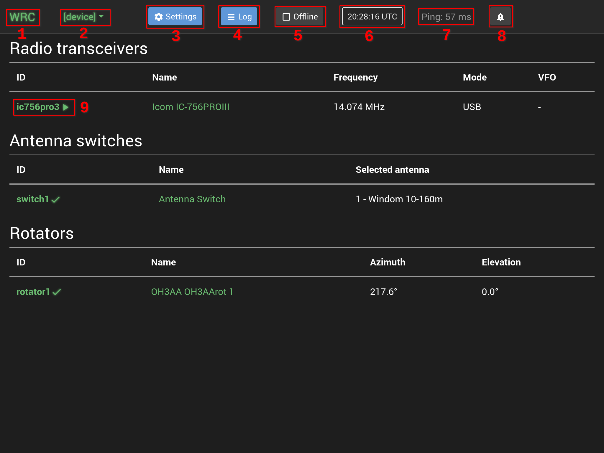
The device list view lists every controllable device defined in the configuration of Web Radio Control.
To use and control a device, click the green device ID or the name of the device to open the control view for
that particular device. There is also a shortcut menu ([device]) in the menu bar at the top of the user interface
for navigating between the available device control views. The text WRC in the menu bar is a link back to
the device list view.
Menu bar
The menu bar at the top of the user interface provides the following functions:
1) The text "WRC"
Clicking the text WRC navigates back to the device list view.
2) Shortcut menu for devices
The shortcut menu for devices ([device]) allows you to navigate directly to the control view of any available device.
3) Settings button
The Settings button opens the settings window for managing Web Radio Control server settings.
4) Log button
The Log button opens the log window that displays technical log data about the Web Radio Control user interface and server
and any startup errors that have occurred during the startup procedures of the Web Radio Control server software.
5) Offline button
The Offline button activates the Offline mode, which disconnects the user interface from the Web Radio Control server.
Clicking the button again will restore the connection.
6) Clock
The clock displays the current time on the client device (web browser). Clicking the clock will toggle the displayed time between the local time zone and UTC time.
7) Ping - network latency
The ping time indicates network latency: the time it takes for a message from the client device web browser
to reach the Web Radio Control server and the time it takes for a response message from the server to reach
the client device. The time includes the duration of a full round-trip of data over the network, so that
data transfer in one direction takes approximately half of the measured ping time.
The remote control network connection quality is good if the latency is under 100 milliseconds. A latency of under 300 milliseconds is usually acceptable and does not heavily interfere with remote control commands or audio transfer. A large ping latency time is indicated with a red color.
8) Bell icon
The bell icon opens the notifications window, which displays detailed information about errors detected during remote control operations.
Device list
The device list displays a list of all controllable devices defined in the Web Radio Control configuration. The list consists of device identifiers (IDs), device model and some essential information about the state of the device, such as the VFO frequency for radios, the current direction for antenna rotators and the selected antenna for antenna switches.
9) Device identifier and remote control state
The first column of the list indicates the device identifier (ID) and the state of remote control:
-
A green check mark indicates that remote control is working for the device
-
A yellow exclamation mark indicates that the device is not responding to control commands, but that the background services related to controlling the device, such as Hamlib for radios, are still functional. Some of the possible causes for this error are: the device is powered off or the Web Radio Control configuration for the device is partially incorrect or incompatible with the device.
-
A red cross indicates that the background services responsible for controlling the device are not functioning correctly and that the device is unreachable currently. Some of the possible causes for this error are: the device is not physically connected to the Web Radio Control server computer (Raspberry Pi), the device is powered off or the Web Radio Control configuration for the device is partially incorrect or incompatible with the device.
You can find more information about solving device remote control issues on the troubleshooting page.
Radio control view
Web Radio Control polls most commonly used radio state settings, such as VFO frequency and mode, every half a second and updates the radio control view to match the radio state if the radio is used outside of Web Radio Control. Additionally, Web Radio Control monitors radio meters, such as the S meter and the SWR meter, approximately 4-5 times a second. The rest of the radio state settings update only when explicitly refreshed. This includes all radio settings in the sidebar, which you can refresh using the refresh button at the top of the sidebar.
The following settings update every half a second:
-
VFO frequency
-
Mode
-
Filter
-
Antenna selection (internal to radio)
-
RIT and XIT frequencies
-
PTT state
-
Split state
The following meters update approximately 4-5 times a second:
-
S meter
-
SWR meter
-
ALC meter
-
RF output power meter
-
Audio compression meter
-
Input voltage meter
-
Current draw meter
-
SQL state (Squelch ON/OFF)
The radio state settings are color-coded in the following way: their color is green when it matches the state of the radio device being controlled. When you change any setting, such as the VFO frequency, in the Web Radio Control user interface, its color changes temporarily to amber until the state of the actual radio transceiver device has changed to match the user interface. This change of color helps you to recognize the latency of remote control and it allows you to verify that the state of the radio device has really changed to what you have requested when the setting color changes back to green.
Some radio transceiver models have "set-only" settings, which means that their state can be set via remote control commands,
but their state cannot be queried. The radio control view indicates these set-only settings with
a question mark ? next to the value of the setting. An example of set-only settings is the VFO setting in most Icom radios,
where the VFO (A or B) can be selected, but the radio does not indicate which VFO is currently selected. The radio control
user interface will display the last VFO setting that was selected in this case.
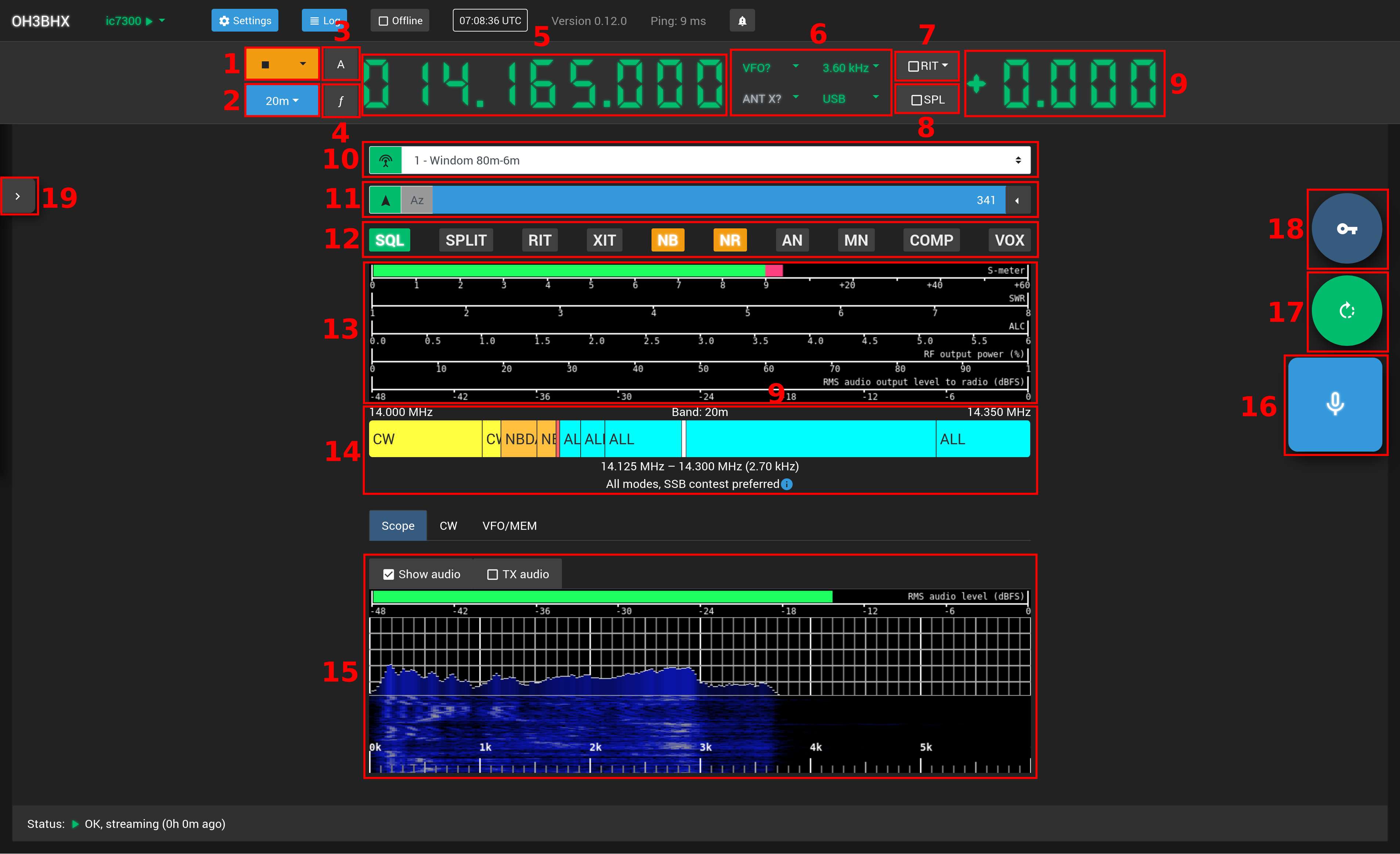
Many commonly used radio functions have keyboard shortcuts.
1) Audio stream control
The blue Play button on the left side starts audio streaming for reception (RX) and transmission (TX)
between the client device web browser and the radio transceiver device. The button color changes to amber
when the audio stream is active and clicking the amber Stop button will stop both audio streaming in both directions.
The drop-down menu on the right side opens a menu, which allows you to control audio streaming in a more fine-grained way. You can start or stop the individual audio streams used for either reception (RX) or transmission (TX). For example, if you do not plan to transmit audio, it is possible to start the stream for audio reception only, which will reduce the amount of network traffic generated by the web browser.
The menu provides settings for audio volumes of the received and transmitted audio. These volume settings control the audio volume in the web browser only and do not control the radio transceiver device in any way.
The TX audio settings section indicates the web browser audio processing functions, such as echo and noise cancellation,
currently being applied for transmitted audio. This audio processing happens entirely in the web browser and the
supported processing functionality depends on the web browser being used. You can change these settings in the
Settings window tab Audio devices. You will need to restart audio streaming to take new audio processing
settings into use.
2) Band selector
The band selector drop-down menu allows fast switching between amateur radio frequency bands. The currently available set of bands includes IARU Region 1 band definitions from 2200m (136 kHz) to 13cm (2.4 GHz). Future versions of the Web Radio Control software will include more bands and support for multiple IARU Regions.
Web Radio Control automatically saves the VFO frequency, mode, filter and the selected antenna for each band, so that when you return to a band you have used before, the previous settings on that band will be restored.
3) A/B VFO selector
The A/B VFO selector button controls which VFO the frequency, mode and filter settings control.
When the selector is indicates VFO B, the frequency, mode and filter settings control the state
of the "opposite" VFO (depending on the currently selected VFO). This selector button does not
change the active VFO, which allows, for example, setting the split frequency without
having to activate the other VFO. As the active VFO never changes, the audio reception in the radio
stays on the same VFO frequency all the time.
4) f button for saved frequencies
The f button opens the window for managing saved frequencies (sometimes called memory channels).
This user guide has a dedicated section that documents the functions available in the saved frequencies window.
The saved frequencies window allows you also to set the current VFO frequency by typing the frequency.
5) VFO frequency display
The VFO frequency display controls the frequency of the active VFO or the opposite VFO depending on the A/B VFO selector state.
You can change the VFO frequency by adjusting the individual digits. Left clicking the mouse or scrolling the mouse wheel up will increase the selected digit and right clicking or scrolling the mouse wheel down will decrease the selected digit.
There is a separate VFO wheel available for use with touch screens.
6) VFO, ANT, filter and mode settings
The VFO settings indicates the active VFO (e.g. A / B / Main / Sub) and you can change the active VFO by clicking the setting, which will display a drop-down menu of available VFOs.
The ANT setting indicates the selected antenna as a number and you can change the selected antenna by clicking the setting, which will display a drop-down menu of available antenna choices. This antenna setting is for selecting the active antenna among the built-in antenna connectors of the radio transceiver. The list of available antennas will always display five antennas, because the exact number of antennas is currently not available via the radio control interface Web Radio Control uses.
It is only possible to control settings supported by the radio transceiver model. Settings not supported by the radio model will appear greyed out. For example, if the radio model has only a single antenna connector, it is not possible to change the selected antenna and the setting will appear as greyed out.
Some radio transceiver models have "set-only" settings, which means that their state can be set via remote control commands,
but their state cannot be queried. The radio control view indicates these set-only settings with
a question mark ? next to the value of the setting. An example of set-only settings is the VFO setting in most Icom radios,
where the VFO (A or B) can be selected, but the radio does not indicate which VFO is currently selected. The radio control
user interface will display the last VFO setting that was selected in this case.
7) RIT/XIT menu
The RIT/XIT menu allows you to enable and disable RIT (Receiver Incremental Tuning) and XIT (Transmitter Incremental Tuning) settings. To select the frequency displayed by the RIT/XIT frequency display next to this menu, click the RIT/XIT text in the menu. The dark blue background in the menu indicates the currently selected frequency (RIT or XIT).
It is only possible to control the RIT and/or XIT settings if the radio transceiver model supports these features. Settings not supported by the radio model will appear greyed out.
8) SPLIT button
The SPLIT button allows you to enable or disable the split function in the radio.
Some radio transceiver models have "set-only" settings, which means that their state can be set via remote control commands,
but their state cannot be queried. The radio control view indicates these set-only settings with
a question mark ? next to the value of the setting.
9) RIT/XIT frequency display
The RIT/XIT frequency display indicates the current RIT or XIT frequency depending on the selection in the RIT/XIT menu.
The RIT/XIT frequency can be adjusted using mouse the same way as the main VFO frequency.
There is a separate frequency wheel for adjusting RIT and XIT on touch screens.
10) Antenna selector (linked antenna switch)
To make antenna switch control faster and easier, Web Radio Control allows you to link antenna switches to one or more radios. When an antenna switch is linked to a radio, a drop-down selector for the antenna switch will appear in the radio control view above the radio meters. The selector lists the available antenna choices for the antenna switch and allows you to change the active antenna simply by selecting one of the antennas in the drop-down selector.
See more details about configuring linked antenna switches.
11) Antenna rotator control (linked antenna rotator)
To make rotator control faster and easier, Web Radio Control allows you to link rotators to one or more radios. When a rotator is linked to a radio, a direction indicator for the rotator direction will appear in the radio control view above the radio meters. The indicator displays the current azimuth and/or elevation (depending on rotator type) and allows you to set the azimuth and elevation angles by clicking the respective numbers.
There is also a drop-down menu shortcut to the saved rotator directions on the right side of the indicator.
See more details about configuring linked antenna rotators.
12) Quick-access indicators and functions buttons for radio
The quick-access indicators and function buttons allow easy access to the squelch status and to some other commonly used functions. Clicking the buttons will toggle the function state.
The following indicators are available, depending on the features supported by the radio:
-
SQL - Squelch status (read-only)
-
SPLIT - Split ON/OFF
-
RIT - RIT ON/OFF
-
XIT - XIT ON/OFF
-
NB - Noise blanker ON/OFF
-
NR - Noise reduction ON/OFF
-
AN - Automatic notch filter ON/OFF
-
MN - Manual notch filter ON/OFF
-
COMP - Audio compressor ON/OFF
-
VOX - Voice-operated relay ON/OFF
13) Radio meters
The radio meters provide feedback about received and transmitter signals. The set of available meters
depends on the meters supported by the radio transceiver model control commands. This set of meters
can be adjusted further with the selection of displayed meters in the Meters section of the sidebar menu.
Web Radio Control supports monitoring the following meters for radios:
-
S meter for received signal strength
-
SWR meter (Standing Wave Ratio) for indicating the standing wave ratio of the transmitted signal
-
ALC meter (Audio Level Control) for indicating the amount of level control required to reduce the strength of the transmitted signal
-
Audio compression meter for indicating the amount of compression applied to the transmitted signal
-
Input voltage meter for indicating the radio voltage. Some radio transceiver models only provide the voltage while transmitting.
-
Current draw meter for indicating the radio current consumption. Some radio transceiver models only provide the current draw while transmitting.
-
RMS audio output level to radio indicates the level of audio that the Web Radio Control server computer outputs to the radio.
You can adjust the set of meters displayed in the Meters section of the sidebar menu.
14) Band plan
The band plan displays band information for the active amateur radio frequency band between
2200m (136 kHz) and 13cm (2.4 GHz) according to IARU Region 1 regulations. The band plan information includes
allowed modes and the largest allowed bandwidth for transmissions. You can select the current VFO frequency by
clicking the band plan. You can also toggle the visibility of the band plan by clicking the Band plan button
in the sidebar.
15) Audio level meter and waterfall display (Scope tab)
The Scope tab in the radio control view displays an audio level meter and a waterfall display
for the audio frequencies. This waterfall display does not extend to frequencies outside the audio spectrum.
The Show audio checkbox toggles visibility of the meter and the waterfall display for received audio
and the TX audio checkbox toggles visibility for transmitted audio. Audio level meter and waterfall display
for transmitted audio is displayed always when PTT is active.
16) PTT transmit button
The PTT transmit button near the right edge of the user interface indicates the state of PTT (transmit) and clicking the button will toggle the PTT state. The microphone icon on a blue background indicates reception and the antenna icon on an amber background indicates that transmission is active. A white microphone icon indicates that squelch is open and a black microphone icon indicates that squelch is closed.
There are two ways to use the PTT transmit button:
-
A short click of the PTT button toggles the PTT state permanently between reception and transmission
-
By pressing the PTT button for a longer duration (over 800 milliseconds), the PTT state will toggle temporarily so that PTT is deactivated immediately when the button is no longer pressed.
17) VFO frequency wheel for touch screens
The green button with a circular arrow icon near the right edge of the user interface toggles the visibility of the VFO frequency wheel for touch screens.
This user guide has a dedicated section that documents the functions available in the VFO frequency wheel.
18) Morse key for touch screens
The dark blue button with a key icon near the right edge of the user interface toggles the visibility of the morse key for touch screens.
This method for keying morse code is suitable for slow keying only, because keying on a touch screen is not very accurate.
This user guide has a dedicated section that documents the morse key for touch screens.
19) Sidebar / radio settings
The arrow button at the left edge of the user interface toggles visibility of the sidebar, which provides control for radio-specific settings and other additional functions related to the user interface and the radio.
This user guide has a dedicated section that documents the functions available in the sidebar.
Radio VFO frequency wheel for touch screen
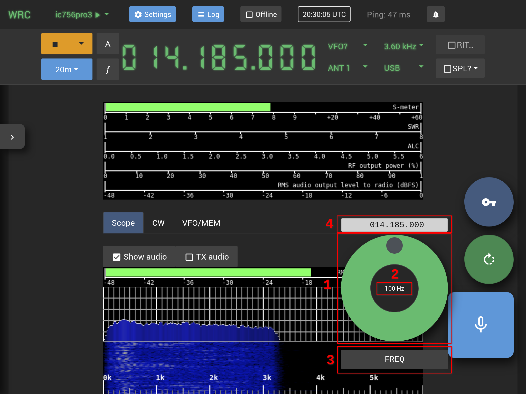
The green button with a circular arrow icon near the right edge of the user interface toggles the visibility of the VFO frequency wheel for touch screens.
1) VFO frequency wheel
To change the VFO frequency, you can "roll" the green VFO wheel on the touch screen. Rolling the wheel clockwise increases the frequency and rolling it counter-clockwise decreases the frequency.
2) Tuning step
The currently selected tuning step is at the center of the VFO frequency wheel. Tapping the tuning step will choose the next tuning step from the following choices: 1 Hz, 10 Hz, 100 Hz, 1 kHz, 10 kHz, 12.5 kHz, 25 kHz and 100 kHz.
3) The name of the active frequency
The name of the active frequency is below the VFO frequency wheel. This choice determines the frequency that the wheel controls.
You can change the active frequency name by clicking the name. The possible frequencies are FREQ (the active VFO),
SPLIT (the opposite VFO), RIT, XIT and RPTR SHIFT (repeater shift). The available frequency choices depend
on the features supported by the radio transceiver model.
4) Frequency display
The value of the active frequency controlled by the wheel is displayed above the VFO frequency wheel. This frequency depends on the selected name of the active frequency.
Sidebar for radio-specific settings
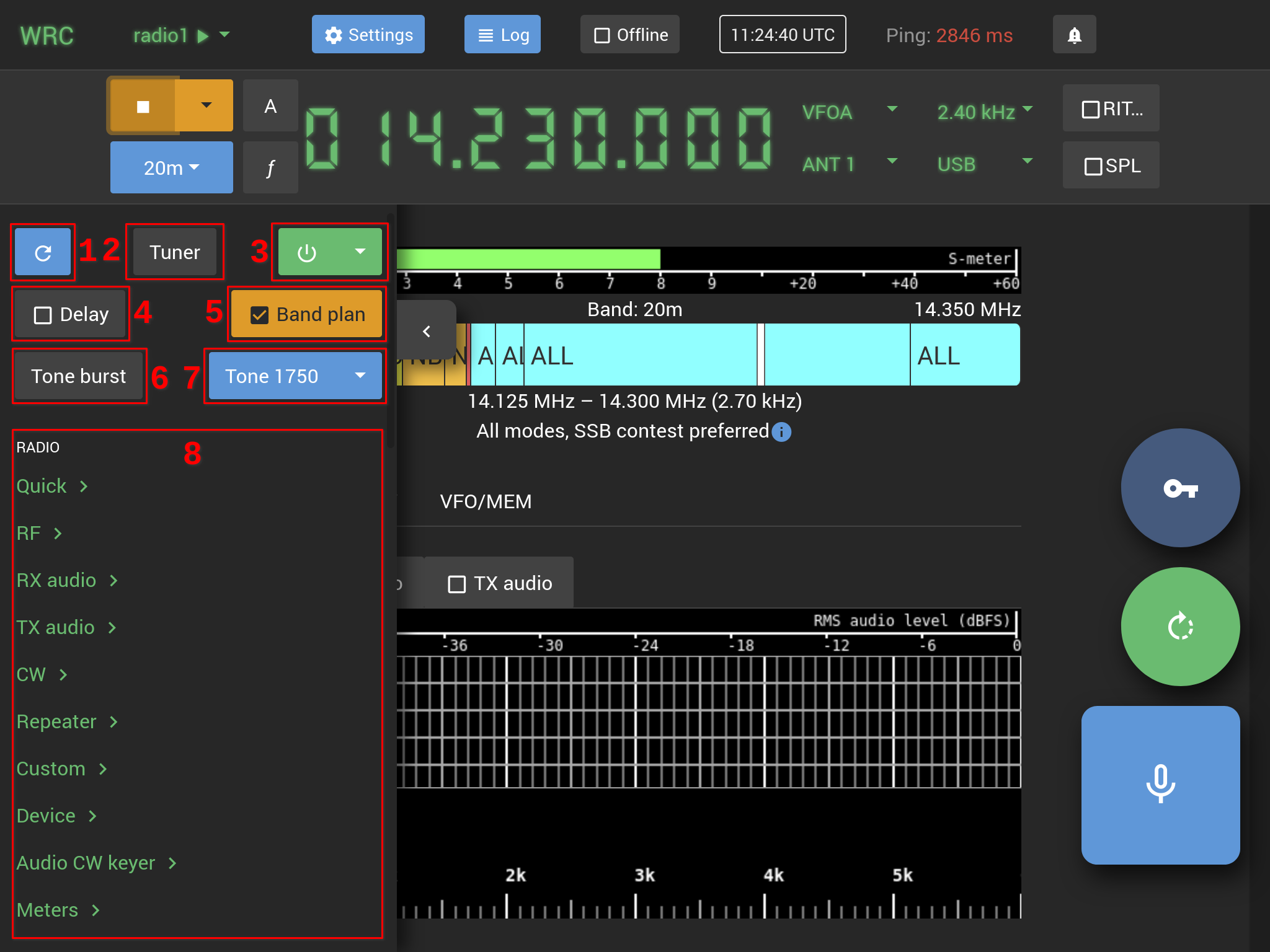
The arrow button at the left edge of the user interface toggles visibility of the sidebar, which provides control for radio-specific settings and other additional functions related to the user interface and the radio.
The upper part of the sidebar provides additional functions for the user interface and the radio:
1) Refresh button
The Refresh button reads and refreshes the radio settings available in the sidebar submenus. Web Radio Control refreshes the values of these settings only when requested, because monitoring tens or hundreds of radio settings actively is a very slow process. In addition to clicking the Refresh button, opening the sidebar automatically refreshes the settings.
2) Tuner button
The Tuner button starts a tuning cycle for the currently active VFO frequency using the automatic antenna tuner in the radio. Many radio transceiver models indicate PTT being active, provide SWR meter readings while tuning is in progress. You may additionally hear the tuning sidetone audio.
The Tuner button is enabled only for radio models, which support controlling the automatic antenna tuner via control commands.
3) Power button
The Power button color is green when the radio transceiver is powered on and ready for use. The button color is red when the radio is powered off or when Web Radio Control is unable to control the radio, because it is often not possible to detect the difference between these two states.
Many radio transceiver models can be powered off via control commands (when the power button is green). How the radio functions when it is powered off depends on the radio model. Some newer radio models have a stand-by state, which allows them to respond to control commands, so that it is possible to power on the radio using a control command (when the power button is red). Some older radio models can be powered on only by applying a voltage to a certain pin via a relay. Please see the documentation of your radio model to check how it works regarding power on/off commands.
The Power button is enabled only for radio models, which support powering the rig on and off via control commands.
4) Delay button
The Delay button allows you to toggle the use of an additional delay in control of radio VFO frequency. When enabled, it reduces the number of control commands sent to the radio when tuning the VFO frequency. The result of this is that "spinning" the VFO fast does not immediately change the radio VFO frequency, which may be necessary with some radio models that respond very slowly to VFO frequency changes. Web Radio Control indicates the additional delay in VFO frequency control using blue color for the VFO frequency.
5) Band plan button
The Band plan button toggles the visibility of band plan information below the radio meters. See the radio device view documentation for more details on how to use this feature.
6) Tone burst button (hardware-based)
The dark grey Tone burst button activates the radio hardware-based tone burst to access a repeater. The tone burst is active only when the button is being pressed.
The Tone burst button is enabled only for radio models, which support hardware-based tone burst via control commands.
7) Tone button (audio, software-based)
The blue Tone button generates sine wave for a tone burst using the web browser audio functionality. This feature can be used with radio models that do not have support a hardware-based tone burst. You can choose the tone burst frequency from the drop-down menu next to the button. The available tone burst frequencies are: 1750 Hz and 2135 Hz. The tone burst is active only when the button is being pressed.
Note that in order to use this software-based tone burst, audio streaming must be active so that the generated tone burst audio will be transferred to the radio to be transmitted.
8) Radio-specific settings
You can access the radio-specific settings in the sidebar submenus. The settings available in the submenus depend on the features supported by the radio model. Additionally, some rarely used settings may not yet be available for remote control because the corresponding control commands are missing from the radio control service (e.g. Hamlib). Support for new radio settings can be introduced through Web Radio Control software updates.
Web Radio Control provides the following submenus for radio-specific settings:
-
Quick- A shortcut menu for user favorite settings. The star icon next to each setting name indicates if the setting will be included in this menu. Clicking the icon will either add or remove the setting from this shortcut menu. -
RF- RF level transmission and reception settings, such as output power level, RF gain and AGC. -
RX audio- Audio reception settings, such as squelch, noise blanker and notch. -
TX audio- Audio transmission settings, such as mic gain, compression and VOX. -
CW- Morse code settings, such as sidetone frequency, keyer speed and break-in settings. -
Repeater- Repeater-related settings, such as CTCSS/DCS tones and repeater offset. -
Custom- Settings that are specific to this particular radio model, which may not be available in other models. This kind of settings are available only some radio models. -
Device- General settings related to the use of the radio device, such as automatic antenna tuner control, button lock, backlight, etc. -
Audio CW keyer- Settings for Web Radio Control audio-based morse keyer. This user guide has a dedicated section that documents the functionality of the audio CW keyer. -
Meters- Settings for configuring the radio meters in the radio control view user interface. You can control which meters are visible in the radio control view using these settings. This user guide has a dedicated section that documents the submenu for meters.
Using the radio-specific settings
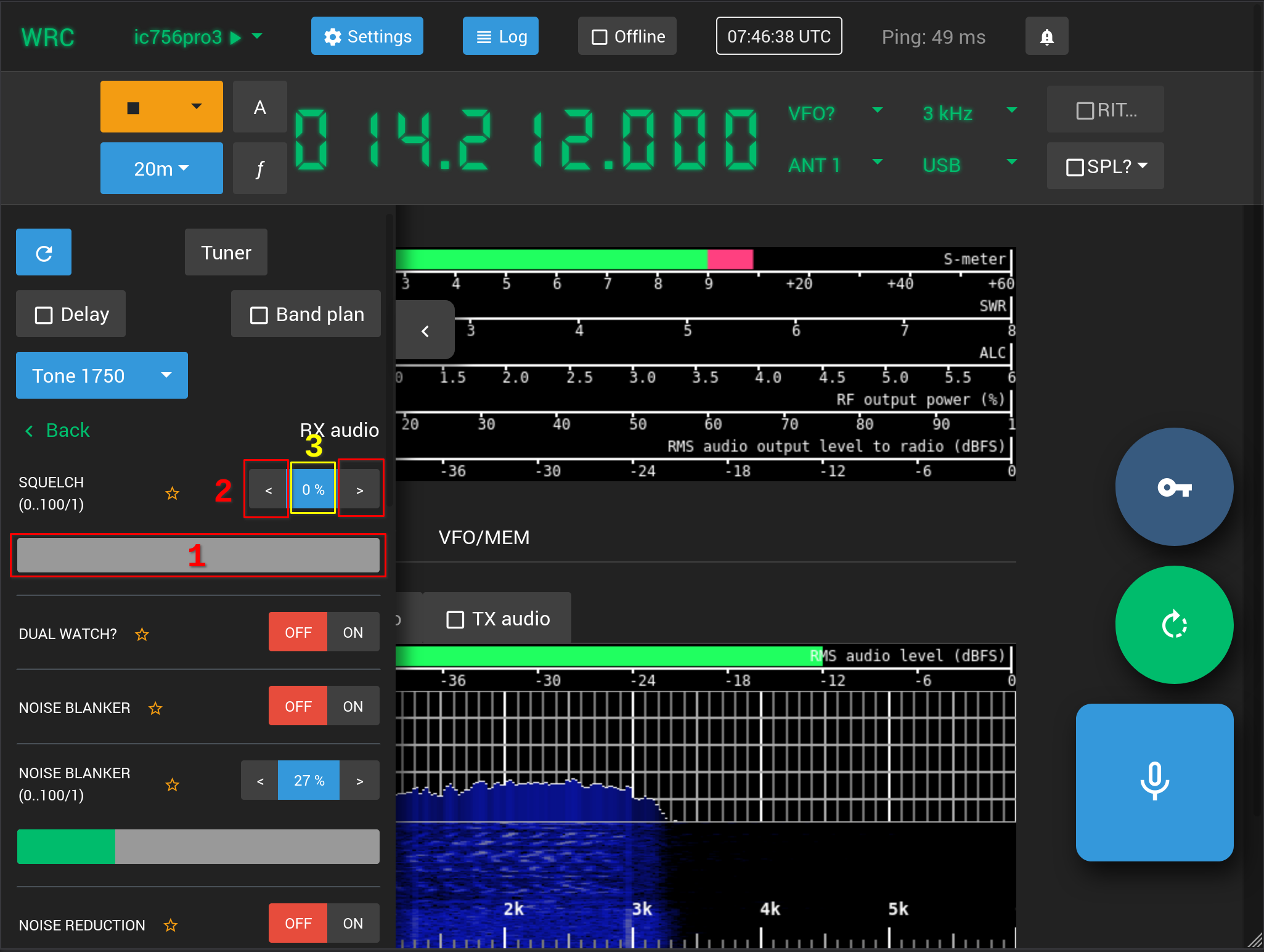
The radio-specific settings can be viewed and changed in the sidebar submenus. The screenshot above displays
the RX audio submenu, which contains settings, such as squelch level, noise blanker and noise blanker level.
Changing the value of a setting depends on the type of the setting:
-
On/Off switch - The on / off switch enables or disables the setting. The OFF text on red background indicates that the setting is disabled and the ON text on green background indicates that the setting is enabled. You can disable the setting by clicking the OFF text and enable the setting by clicking the ON text.
-
Adjustable level - There are three ways to change the value of an adjustable level:
-
1) Clicking the slider bar below the setting name adjusts the level according to the position where the bar was clicked. A double-click sets the level to whatever the value is at the center (often 50%).
-
2) Clicking the arrows on either side of the level value (number) increases or decreases the value by one step. The step size depends on the setting.
-
3) Clicking the level value (number) between the arrows allows you to type the level value digits.
-
-
Drop-down menu - Clicking the drop-down menu displays the available choices for the setting.
Settings for radio meters
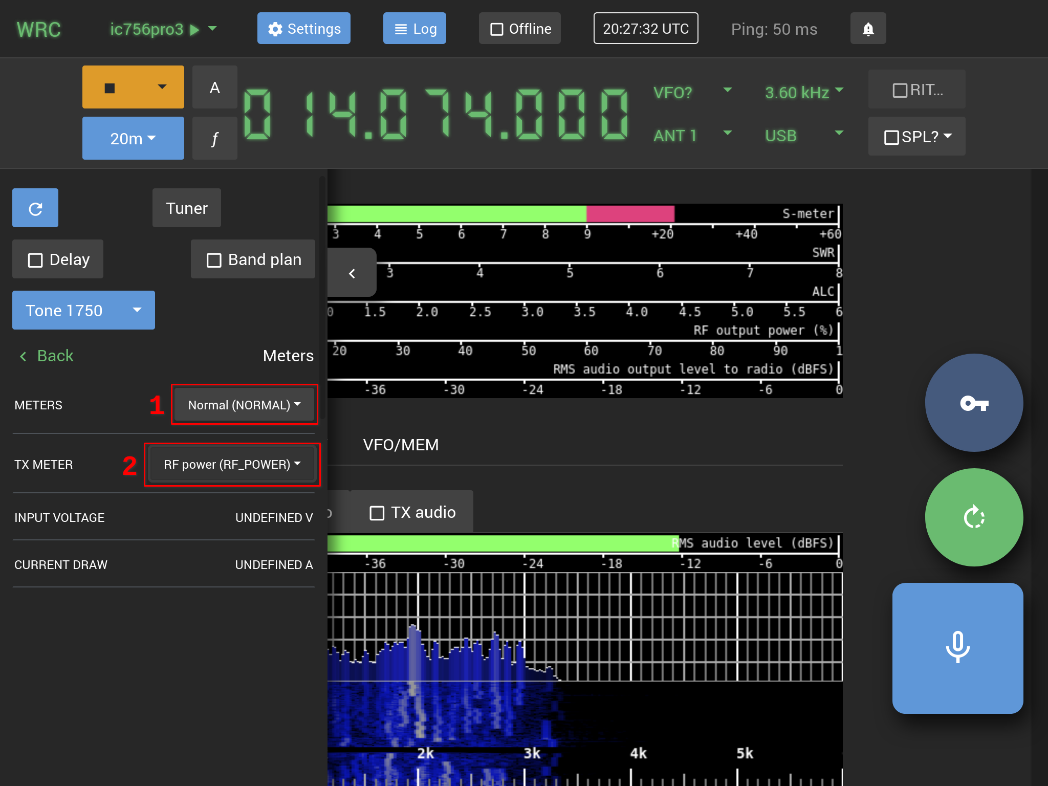
The Meters submenu in the sidebar contains settings for controlling the behavior and visibility of radio meters in the radio control view.
1) The METERS setting drop-down menu provides the following choices to select which meters are visible in the radio control view:
-
The
Normalsetting will display the meters:S-meter,SWR,ALC,RF output powerandRMS audio output level to radio. Some of the meters may be missing if the radio model does not support monitoring a particular meter. -
The
Compactsetting will only display theS-meterduring reception and the meter indicated by theTX METERsetting during transmission. -
The
Allsetting will display all available meters:S-meter,SWR,ALC,RF output power,Audio compression,Input voltage,Current drawandRMS audio output level to radio. Some of the meters may be missing if the radio model does not support monitoring a particular meter.
Saved frequencies for radio
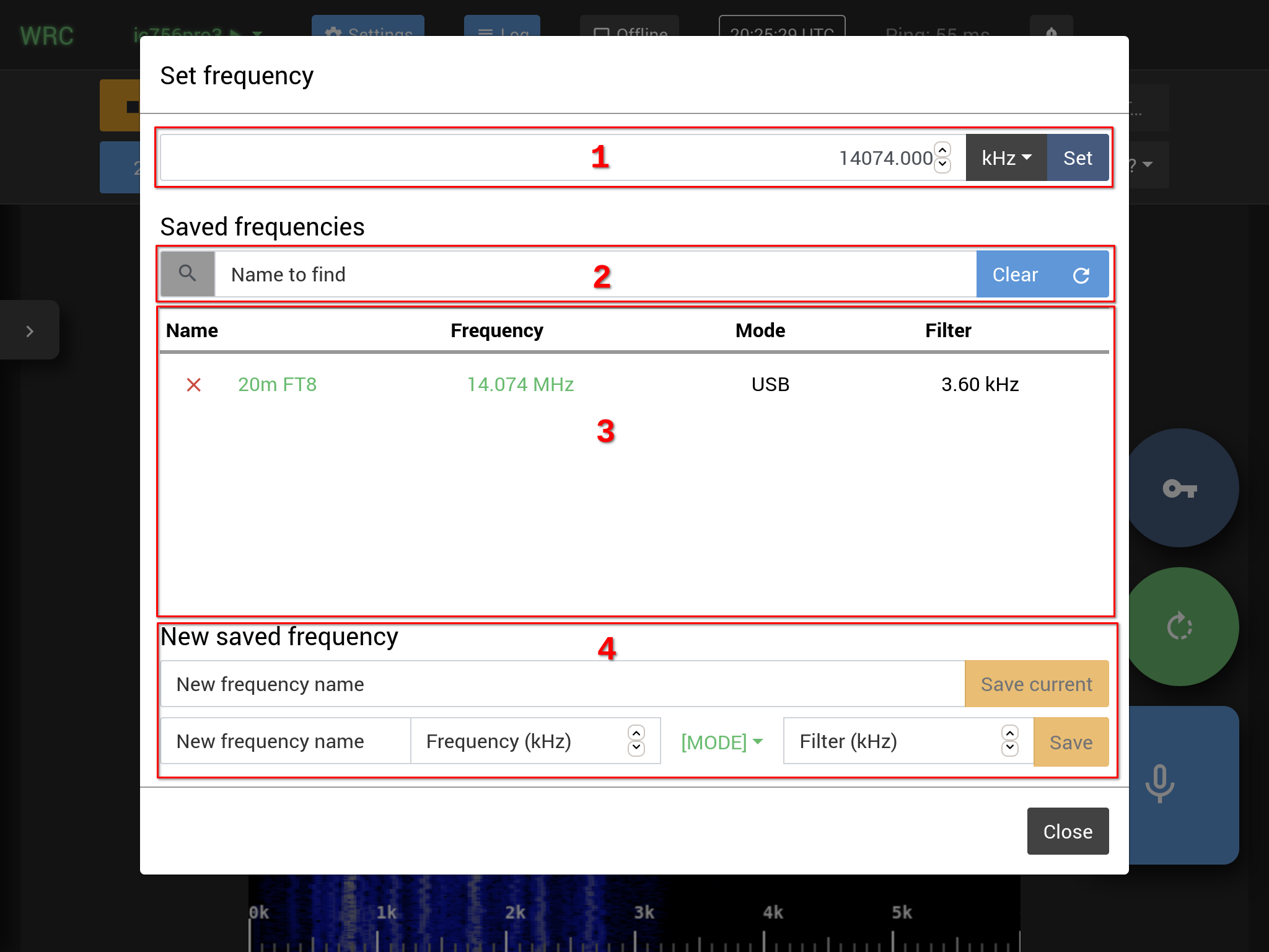
The saved frequencies are a list of snapshots from radio state. This feature is similar to what is called "memory channels" in many radios. Each saved frequency has a user-defined name and the saved state consists of the VFO frequency, the operating mode and the audio filter width choice. The saved frequencies can be searched by name. Web Radio Control stores the saved frequencies internally and they are not related to the built-in memory channels of the radio.
The f button in the radio control view opens the saved frequencies window.
1) Frequency text input field
The frequency text input field indicates the current VFO frequency (depending on the A/B VFO selector). The frequency unit
(Hz / kHz / MHz) depends on the frequency unit drop-down menu selection. The Set button sets the current VFO frequency
according to the frequency text input field value.
2) Saved frequency search
You can search for saved frequencies by typing a part of or the full name of the saved frequency in the text input field
indicated by text Name to find. Typing into the text input field will automatically trigger display
of search results below the text field.
3) Saved frequency list
The list of saved frequencies will contain all saved frequencies by default, or the results of saved frequency search if the text input field for search is not empty. Clicking the saved frequency name will set the current VFO frequency, operating mode and the audio filter width in the radio according to the saved frequency. The red cross on the left side of the saved frequency name will delete the saved frequency.
4) Storing a new saved frequency
The New saved frequency section provides functions for creating new saved frequencies.
There are two ways to create a new saved frequency:
-
Saving the current VFO frequency: The first text input field with button
Save currentsaves the current VFO frequency, the operating mode and the audio filter width choice using the name typed in theNew frequency nametext input field. -
Saving a user-defined frequency: The second text input field with button
Saveallows you to specify the VFO frequency, the operating mode and the audio filter width independently. Only the saved frequency name and the VFO frequency are mandatory: the operating mode and the audio filter width are optional and can be left empty.
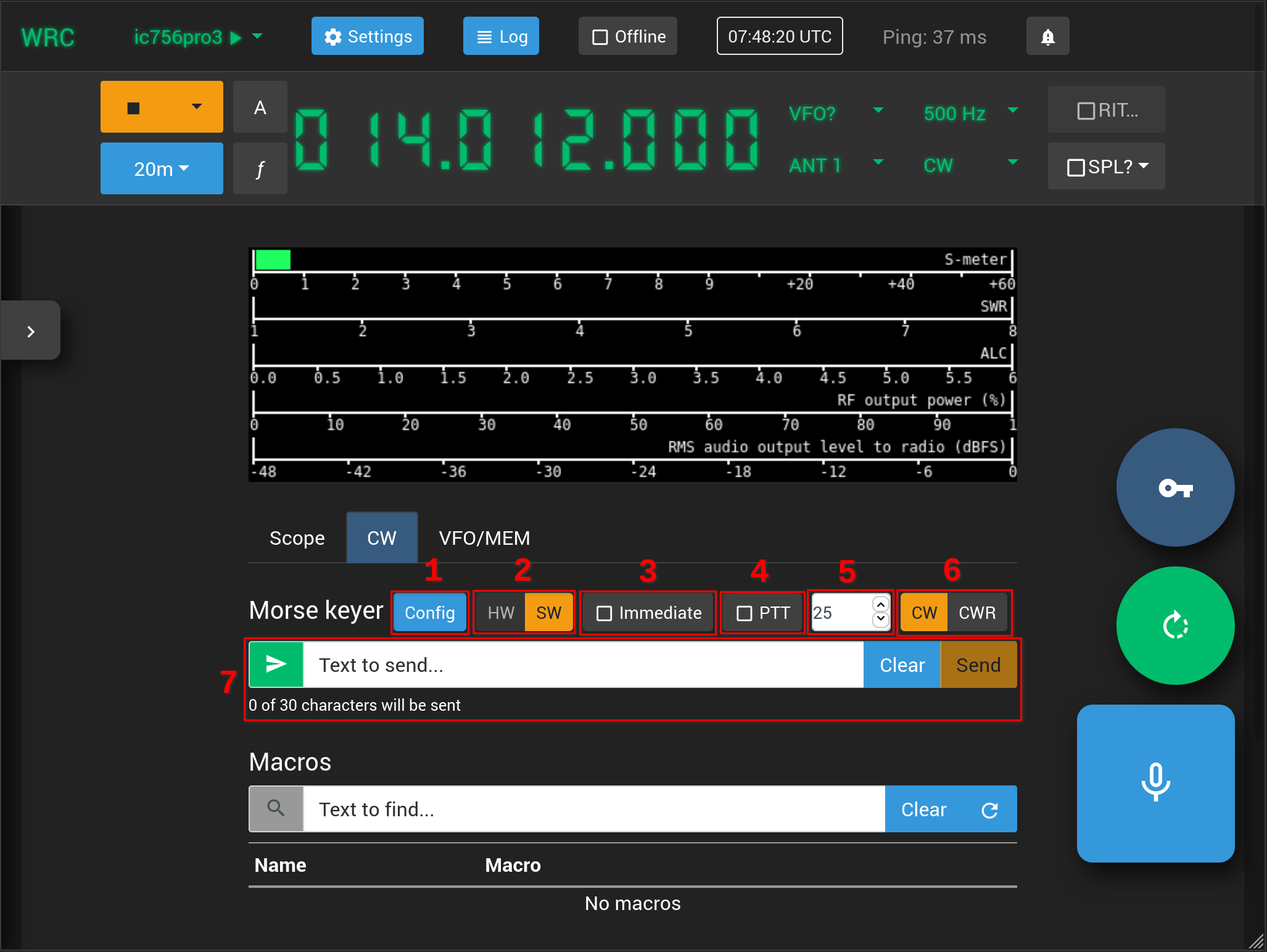
CW: Morse keyer
Web Radio Control supports the following options for keying morse code:
-
HW= hardware mode for keying: More recent radio transceiver models have the ability to perform morse code keying directly from text sent to the radio. In this mode, Web Radio Control sends the text to be keyed directly to the radio and it is the radio that performs the translation from text to morse code. The radio-specific settings (in the sidebarCWsubmenu) determine the speed for keying text in this case. It is only possible to use text-based keying (including macros), which means that use of the USB adapter for a physical morse key is not supported in theHWmode. -
SW= software mode for keying: Most radio transceiver models can perform morse code keying via a dedicated, external keying connector or via RS-232 serial port RTS/DTR control lines. In this mode, Web Radio Control generates the morse code to be keyed either from text entered by an operator or from the signals of a physical morse key connected to the client device via a USB morse key adapter. Web Radio Control internal morse keyer settings determine the speed for keying text.
See more details about configuring CW keyer.
1) Config button
The Config button opens the CW submenu in the sidebar radio-specific settings. This button works as a shortcut
for displaying radio CW settings.
2) HW/SW mode selector
The HW/SW mode selector selects the method for keying morse code. The availability of each mode depends on the radio model features and morse keyer configuration in Web Radio Control.
The HW mode (hardware-based morse keying) uses features available in more recent radio transceiver models,
which can perform keying of morse code directly from text. In this mode, Web Radio Control sends the text
to be keyed directly to the radio and it is the radio that performs the translations from text to morse code.
The radio-specific settings (in the sidebar CW submenu) determine the speed for keying text in this case.
It is only possible to use text-based keying (including macros), which means that use of
the USB adapter for a physical morse key is not supported in the HW mode. The HW mode is selectable
in the radio control user interface only if the radio model supports keying morse code directly from text.
The SW mode (software-based morse keying) performs keying of morse code via a separate, external
keying connector in the radio or via RS-232 serial port RTS/DTR control lines. In this mode,
the Web Radio Control server software generates the morse code to be keyed either from text entered by an operator
or from the signals of a physical morse key connected to the client device via a USB morse key adapter.
Web Radio Control internal morse keyer settings determine the speed for keying text. The SW mode is selectable
in the radio control user interface only if software-based morse keying is correctly configured in Web Radio Control
configuration for the radio: either a GPIO pin or an RS-232 serial port RTS/DTR control line needs to be connected
to the radio.
See more details about configuring CW keyer.
3) Immediate mode button
The Immediate mode button enables or disables a mode, where the text entered to the text input field to be keyed
will be keyed immediately without the need to press the Enter key or to click the Send button.
Any text that is typed faster than the current morse keyer speed will be buffered automatically.
4) PTT control mode button
The PTT control mode button enables or disables a mode, where the radio PTT (transmission) will be separately
activated during keying of morse code. Activating PTT separately may be required by some older radio transceiver models,
which do not support full break-in or semi break-in functions. The CW break-in settings are available in the CW submenu
of the sidebar and enabling either of these settings will automatically trigger PTT internally in the radio.
5) WPM morse keyer speed in SW mode
This input field sets the software morse keyer speed when using the keyer in the SW mode.
The maximum supported keyer speed is 50 WPM (Words Per Minute).
6) CW/CWR operating mode buttons
The CW/CWR operating mode buttons are shortcuts for activating either the CW or CWR mode in the radio.
7) Text input field for morse keyer
Web Radio Control performs morse code keying based on the text in this input field.
In the default mode, the text entered in the input field will be keyed when either the Enter key is pressed
or the Send button is pressed. In the Immediate mode, the text entered in this input field
will be keyed immediately and any text that is typed faster than the current morse keyer speed will be
buffered automatically.
The Clear button empties the text input field.
The Cancel button (a cross on a red background on the left side of the text field) is available while
the morse keyer is active. Pressing the cancel button will stop keying immediately and will clear the
internal keying buffer. Pressing the Esc key when focus is in the text input field will also stop keying.
USB morse key adapter (prototype device)
The USB morse key adapter device is currently at prototype stage and instructions for building one are available in GitHub on the USB morse key adapter building instructions page. The adapter can be connected to a computer, a table or a phone. A USB OTG (on-the-go) adapter is required for most tablets and phones. We are currently developing a more advanced version of the USB morse key adapter and we are looking into the possibility of selling the adapter as a kit!
Web Radio Control allows a regular, physical morse key to be used for keying morse code. The morse key needs to be connected to the client device using a USB morse key adapter designed specifically for use with Web Radio Control. This USB morse key adapter supports both straight keys and dual-lever paddle keys, as the adapter contains an electronic morse keyer. The adapter has a speaker for outputting the CW sidetone and it supports adjustable electronic keyer speed.
The working principle of the USB morse key adapter is simple: the adapter acts as a USB keyboard for
the client device it is connected to and each press its registers from a morse key generates
a key press using the comma key (,) on the client device. The Web Radio Control radio control user interface
monitors the timing and duration of these key presses and sends commands to the Web Radio Control server software
to key the radio according to the timing of the key presses. In theory, it is also possible to use the
comma key on a normal keyboard as a straight morse key, but it is often difficult in practice, because
the physical structure of the keyboard keys makes keying morse code very slow.
CW: Morse code macros
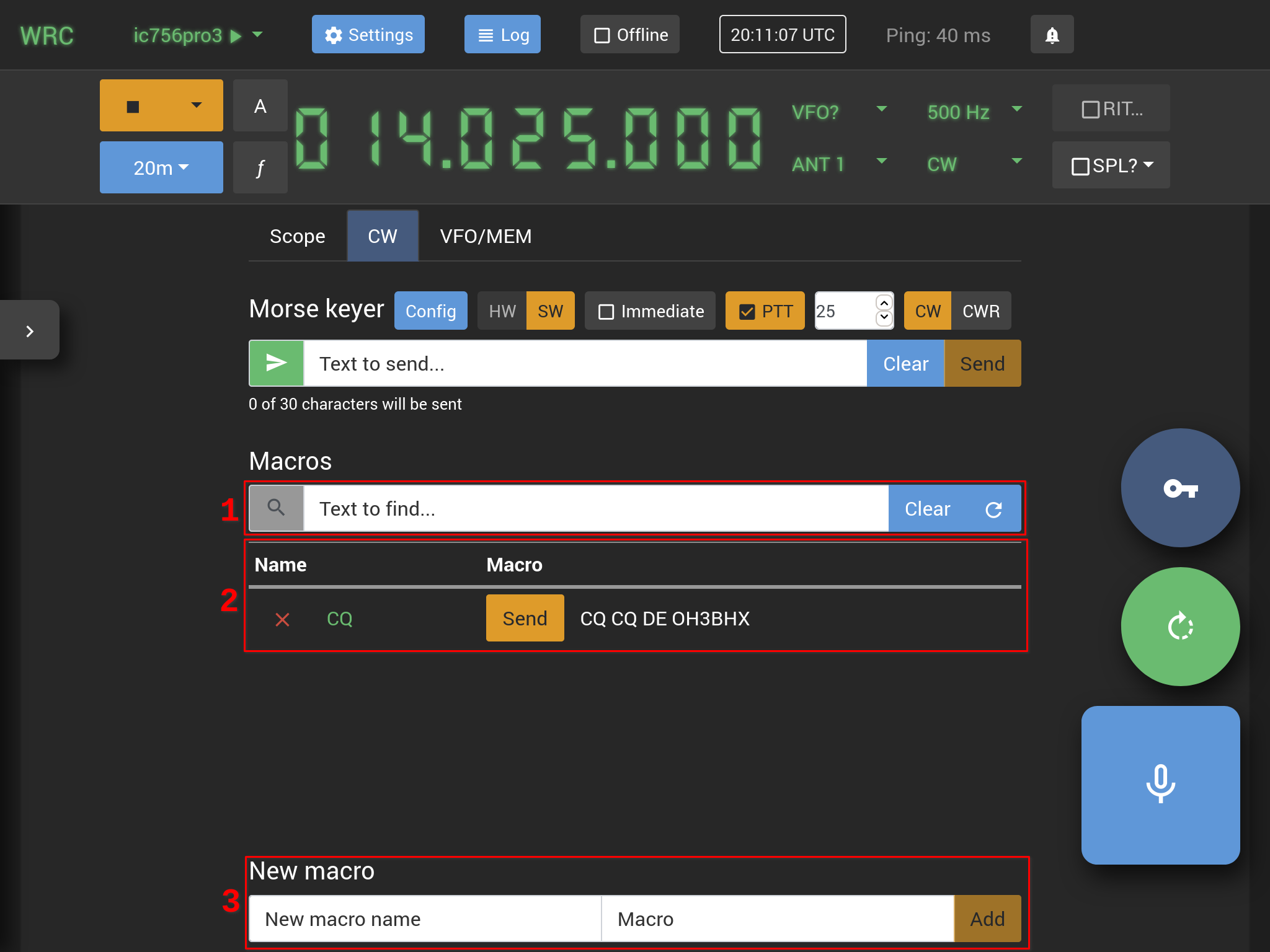
1) Macro search text input field
You can search for morse code macros by typing the macro name or part of the macro text content in the text input field
indicated by text Text to find. Typing into the text input field will automatically trigger display
of search results below the text field.
2) Morse code macro list
The list of morse code macros will contain all macros by default, or the results of macro search
if the text input field for search is not empty. Clicking the Send button on the left side of the macro name
will trigger keying of the macro text on the radio being controlled. Clicking the macro name will copy the
macro text contents to the above text input field for morse keyer, which allows you to edit the text before keying.
The red cross on the left side of the macro name name will delete the macro.
3) Storing a new macro
The New macro section provides functions for storing new macros.
Type the macro name in the text input field indicated by text New macro name and the text content
of the macro in the text input field indicated by text Macro. Click the Add button to store the new macro.
CW: Keying morse code using touch screen or keyboard
Keying of morse code using touch screen or keyboard is designed to be used as a backup if there are no better options available for keying CW. While it is possible to use a touch screen or the keys of a computer keyboard as a morse key, these methods make keying slightly difficult and allow only slow keying speeds.
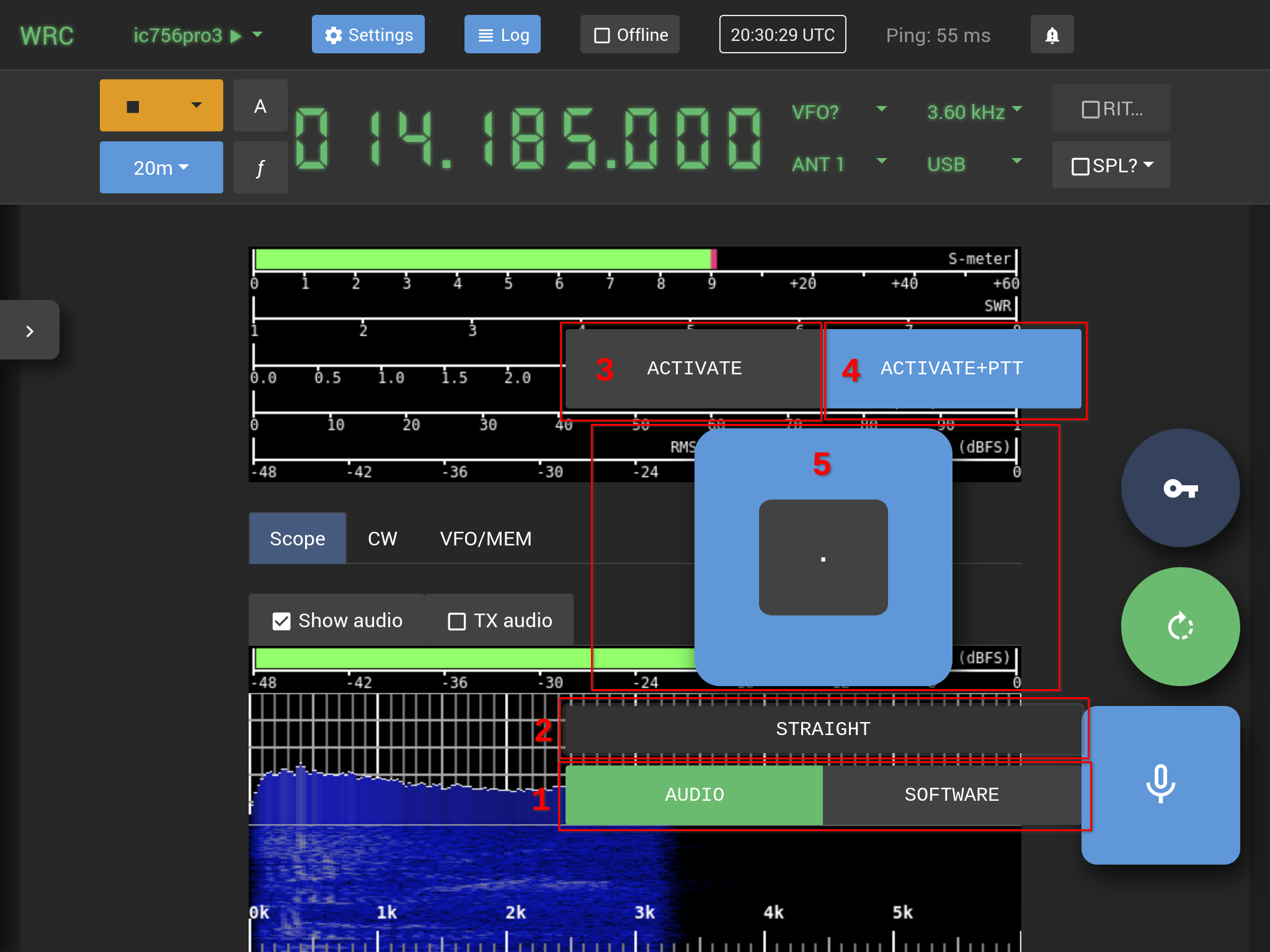
1) Audio/Software selector buttons
The Audio/Software selector buttons choose the method for keying morse code:
-
The
Audiomode generates audio-based CW, where the web browsers is responsible for generating sine wave to represent the CW carrier wave. This method works only in SSB operating mode and requires audio streaming to be active so that the generated audio will be delivered to the radio for transmission. The audio CW functionality is designed to be used as a backup if there are no better options available for keying CW. -
The
Softwaremode is equivalent to theSW(software keying) mode in theCWtab in the radio control view, where Web Radio Control user interface monitors the timing of the on-screen morse key presses and sends them to Web Radio Control server software to be keyed on the radio via a serial port control line or via a GPIO pin connected to the radio CW keying connector. This mode is available only if the Web Radio Control configuration for the radio contains settings that enable keying via an RS-232 serial port control line or via a GPIO pin for the radio according to the CW keyer configuration instructions.
2) Touch screen morse key type selector
There are three morse key types available in the Audio keying mode:
-
STRAIGHT- the touch screen morse key functions as a straight key -
BUG- the touch screen morse key generates dots automatically, but dash length is determined by the operator -
PADDLE- the touch screen morse key generates both dots and dashes automatically
In Software mode, the only morse key type available is the STRAIGHT key.
3) Activate button
The Activate button enables or disables audio-based CW keying for testing where nothing will be transmitted.
4) Activate+PTT button
The Activate+PTT toggles both audio-based CW keying and PTT, so that the radio will transmit
the CW carrier in the audio when this function is enabled.
5) The dot and dash buttons of the touch screen morse key
The dot and dash buttons acts as the morse key paddles and keying morse code is performed by pressing these buttons.
When the selected morse key type is STRAIGHT, the touch screen morse key consists only of a single button that
acts as a straight key.
Using the keyboard as a morse key
Web Radio Control provides keyboard shortcuts for keying morse code. In order to use the keyboard shortcuts, the Web Radio Control radio control view user interface must be open in the web browser and the cursor must not be active in any text input field. The easiest way to ensure that the user interface "focus" is set correctly is to tap or click the empty background of the user interface.
The following keyboard shortcuts are available in the Audio keying mode:
-
CTRL+ALT+W - Toggle audio keyer and PTT on/off
-
.(dot) - Automatic keyer: dit (dot) -
-(dash) - Automatic keyer: dah (dash) -
/(slash) - Automatic keyer: dah (dash) (for US keyboard layout) -
,(comma) - Straight key
The following keyboard shortcuts are available in the Software keying mode:
-
,(comma) - Straight key
Antenna rotator control view
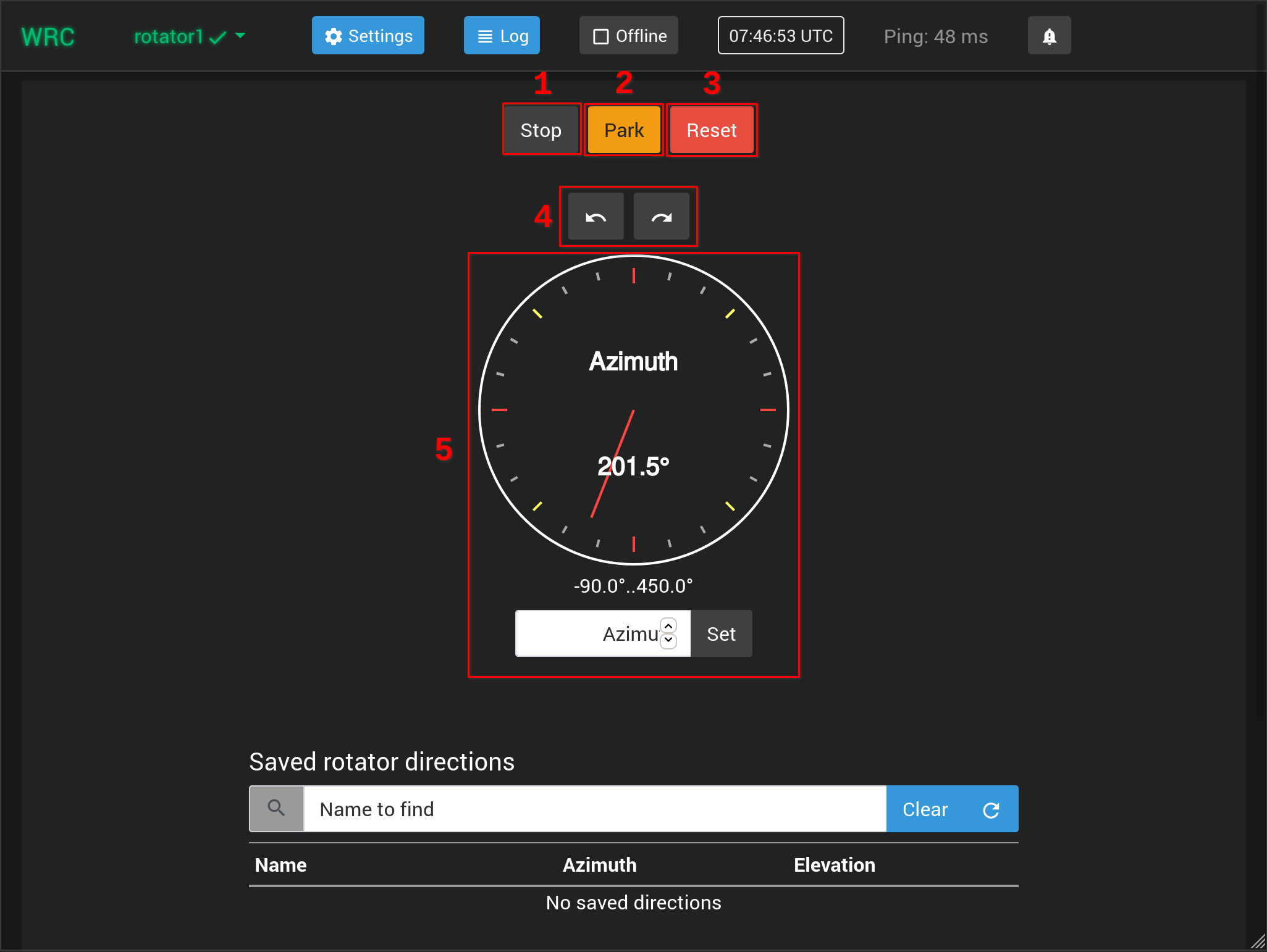
The antenna rotator control view contains the azimuth and/or elevation direction displays depending on the antenna rotator model. It is possible to control the antenna rotator either by setting the antenna direction in degrees or by turning the rotator manually in a specified direction.
If your station has an antenna rotator, but the antenna rotator control view is missing in the Web Radio Control user interface, see more details about configuring antenna rotators.
1) Stop button
Pressing the Stop button stops the antenna rotator.
2) Park button
Pressing the Park button sets the rotator direction to "parking position", which may vary depending on the model
of the antenna rotator. This direction is often zero degrees.
3) Reset button
The Reset button resets the antenna rotator controller state. What this function does depends on
the antenna rotator controller model.
4) Counterclockwise and clockwise buttons
The counterclockwise (CCW) and clockwise (CW) buttons make the antenna rotator turn continuously
to the chosen direction until the Stop button is pressed or another direction is chosen. Many antenna rotators
also have certain limits, which prevent the rotator from turning too far in either direction.
It is recommended to be careful when using the CCW and CW buttons: make sure that the antenna rotator will not accidentally rotate too far, which could result in physical damage to the rotator or the antennas.
5) Azimuth and elevation direction displays
The azimuth and elevation direction displays indicate the current direction of the antenna rotator both as number in degrees and as a graphical pointer. The graphical direction pointer is green when the antenna rotator is idle (not rotating) and the pointer is red when the rotator is rotating the antennas. The available displays depend on the antenna rotator model, which can be an azimuth rotator, an elevation rotator or a combined azimuth and elevation rotator.
The antenna rotator direction can be set in the following to ways:
-
The direction can be set by pointing the desired direction and by clicking the direction display. Before choosing the direction by clicking the display, there is a blue pointer indicating the pointed direction and this direction is displayed as a number in parenthesis under the actual rotator direction.
-
The direction can also be set by typing the direction as a number in degrees in the input text field under the azimuth or the elevation direction display and by pressing the button
Setafter typing the direction.
Saved directions for antenna rotator
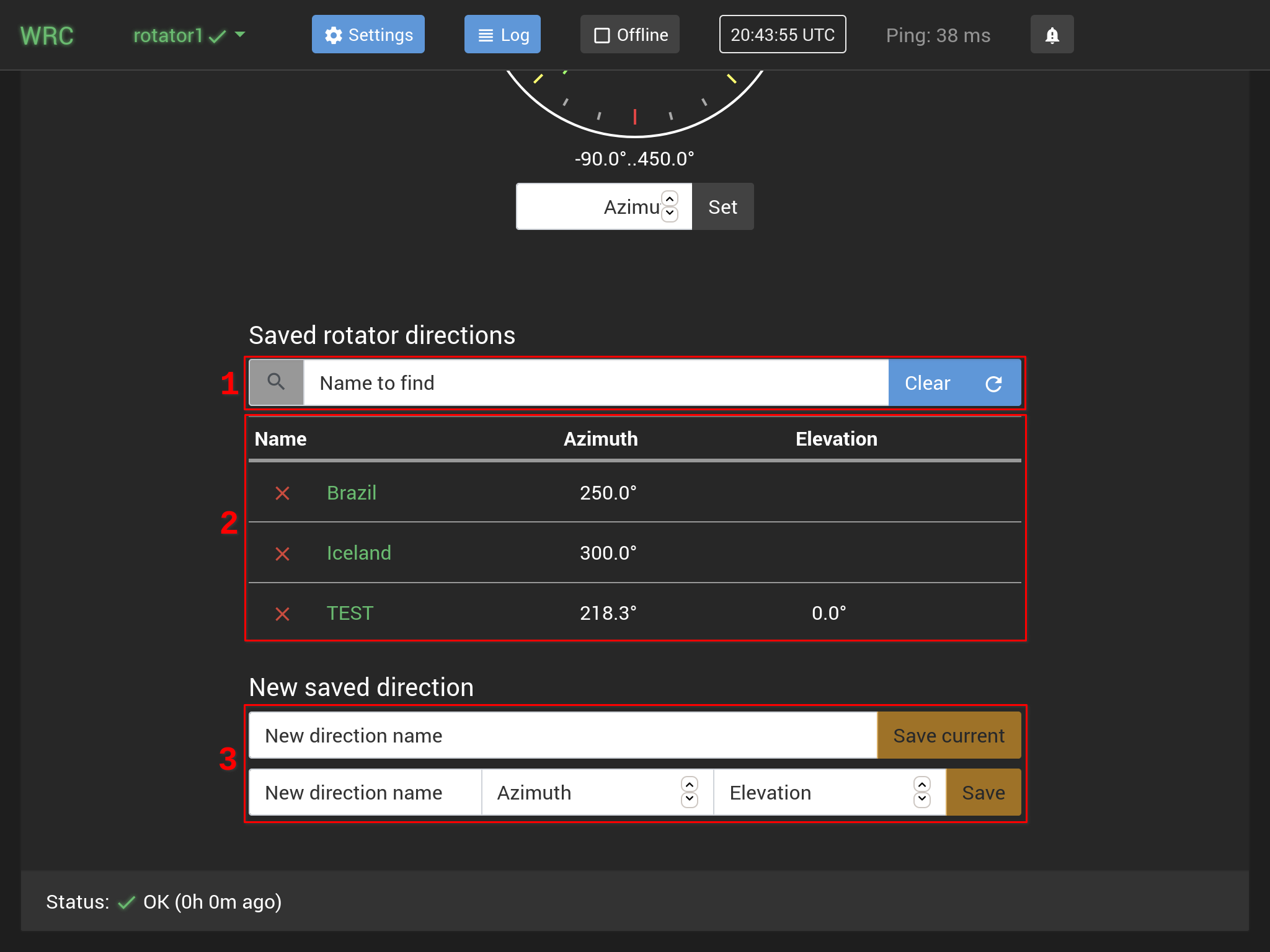
The saved rotator directions are a list of saved rotator direction information that includes either the azimuth, the elevation or both directions in degrees. The saved directions can be searched by name. Web Radio Control stores the saved directions internally and they are not related to any built-in memory in the antenna rotator controller.
1) Saved direction search
You can search for saved directions by typing a part of or the full name of the saved direction in the text input field
indicated by text Name to find. Typing into the text input field will automatically trigger display
of search results below the text field.
2) Saved directions list
The list of saved directions will contain all saved directions by default, or the results of saved direction search if the text input field for search is not empty. Clicking the saved direction name will set begin turning the rotator to the azimuth and elevation directions indicated by the saved direction. The red cross on the left side of the saved direction name will delete the saved direction.
3) Storing a new saved direction
The New saved direction section provides functions for creating new saved directions.
There are two ways to create a new saved direction:
-
Saving the current rotator direction: The first text input field with button
Save currentsaves the current azimuth and/or elevation with the name typed in theNew frequency nametext input field. -
Saving a user-defined rotator direction: The second text input field with button
Saveallows you to specify the azimuth and/or the elevation directions independently. In case of a combined azimuth and elevation rotator, it is possible to store either only the azimuth or the elevation direction or both.
Antenna switch control view
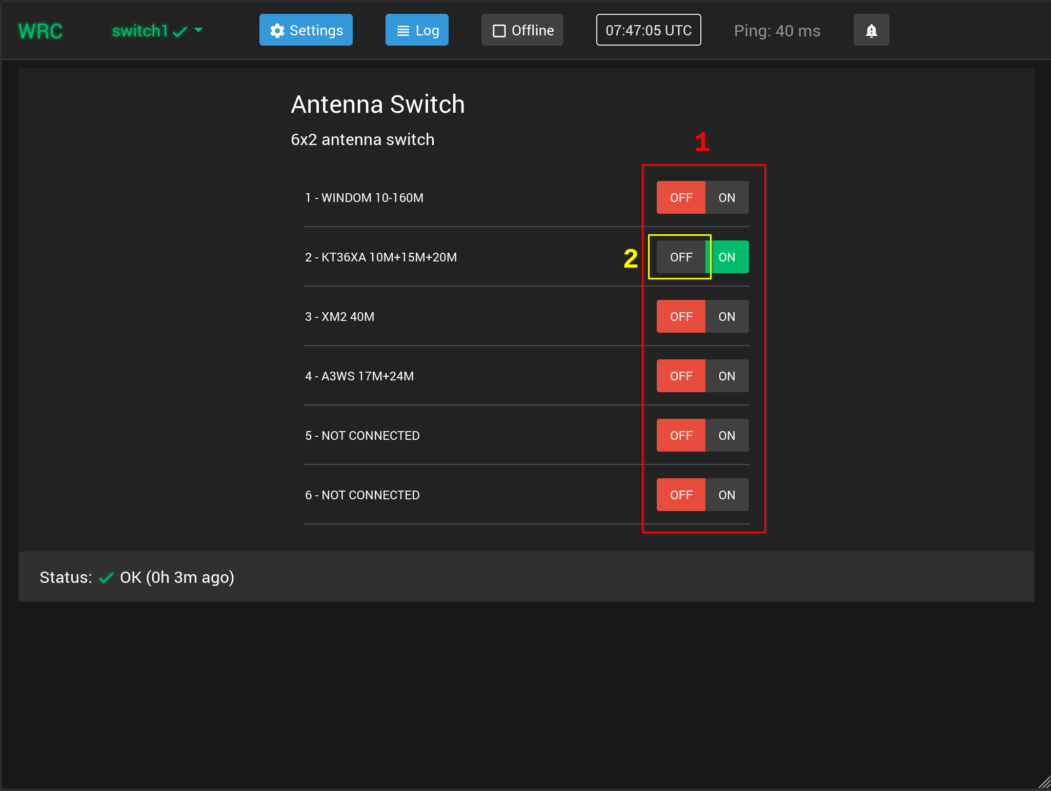
The antenna switch control view lists the antennas available in the switch and allows selecting the active antenna
using the ON/OFF buttons.
Currently, Web Radio Control supports antenna switches connected to a single radio only.
1) ON/OFF buttons
Clicking the ON text makes the selected antenna active and deactivates the previously used antenna.
2) Disconnecting antennas
Some antenna switches have the ability to disconnect all antennas from a radio, where the antenna connection
of the radio will be either left disconnected or it will be grounded. Clicking the OFF text for the antenna that is currently
active removes the antenna selection to allow the antenna switch to disconnect the antennas.
If your station has an antenna switch, but the antenna switch control view is missing in the Web Radio Control user interface, see more details about configuring antenna switches.
Additional user guide documentation
Additional user guide documentation for various topics:
Installing TLS root certificate authority on a new client device
Starting to use Web Radio Control on a new client device requires installation of a TLS root certificate authority in the web browser of the device
Keyboard shortcuts
Keyboard shortcuts for commonly used features
Working digital modes
Instructions on how to connect digital mode applications to Web Radio Control
Upgrade instructions
Upgrading Web Radio Control remote control software to a newer version