3/5: Creating the configuration file
Step 3/5: Creating the configuration file based on the device list
-
Download this configuration file template and save it on the local disk: wrc-config-template.yaml
-
Open the downloaded configuration file template using a text editor application
-
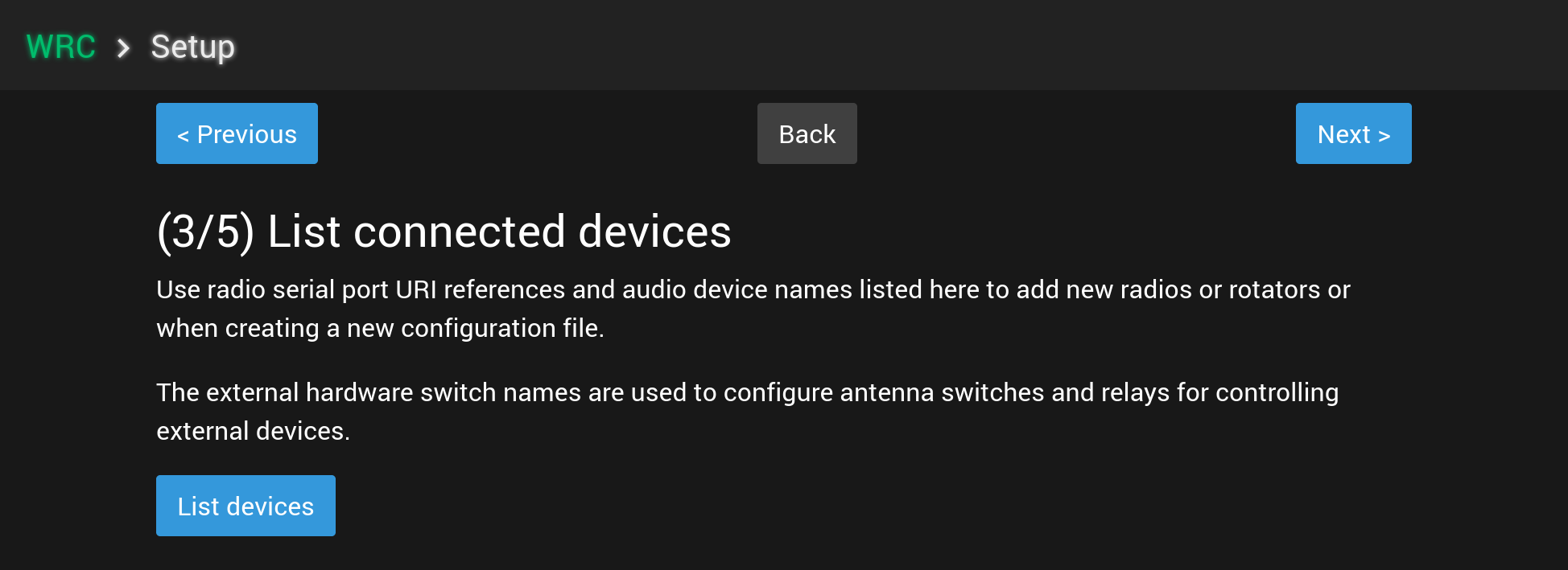
Click the
List devicesbutton in the Web Radio Control setup user interface to list attached USB serial port adapters and USB sound cards
Configuration file template
The text below is a copy of the configuration file template (downloadable from the link above) for documentation purposes:
global:
  uniqueSystemDeviceNames: false

server:
  publicHostname: "DOMAIN_NAME"
  ipv6: false
  lanMode: false
  apiSecret: "PASSWORD"

devices:
- id: "radio1-id"
  type: "rigctld"
  rigctld:
    localInstance:
      enabled: true
      model: RADIO_MODEL_NUMBER
      rigDevice: "SERIAL_PORT_DEVICE"
      serialSpeed: SERIAL_SPEED
  media:
    stream:
      audioInputDeviceName: "AUDIO_INPUT_DEVICE_NAME"
      audioOutputDeviceName: "AUDIO_OUTPUT_DEVICE_NAME"
The configuration file template can be downloaded from: wrc-config-template.yaml
Filling in the configuration file template
Replace the placeholders (e.g. DOMAIN_NAME) in the configuration file template. The placeholders that need to be
replaced are listed below. Please pay attention to preserve any double quotes and spaces around the placeholders.
The configuration file format is called YAML, which is sensitive to the number of spaces in the beginning of each line. Please make sure to not change the number of spaces!
Some of the following placeholders in the configuration file template depend on the radios and other accessories in use,
so you will have to look up them in the List devices listing of the setup user interface.
Configuration options
The placeholders to be replaced in the configuration file template are:
Application-level and networking configuration
-
uniqueSystemDeviceNames- This setting should befalsein most simple station setups, when there is only a single device of each device type (e.g. radio or rotator) to be controlled remotely. The setting allows you to use multiple radios or other peripherals of the same model. Connecting multiple USB devices of the same or similar model may lead to conflicting serial port or audio device names and theuniqueSystemDeviceNamessetting with valuetrueresolves these conflicts by exposing the individual USB ports in the device names. When this setting is enabled, it is necessary to keep each device in the same, dedicated USB port at all times. -
DOMAIN_NAME- Domain name for the Web Radio Control server, which must be the same domain name used for the TLS certificate. -
PASSWORD- Web Radio Control server password for remote control. Please use a password with at least 11 characters, including special characters, but please avoid use of double quotes (") as they may cause issues with the YAML configuration file format. -
ipv6- Web Radio Control uses IPv4 addresses by default (ipv6isfalse). If you wish to use Web Radio Control in an IPv6 network, use valuetruefor theipv6setting. Note that when using IPv6 addresses, also the domain name (theDOMAIN_NAMEreference above) needs to point to an IPv6 address. -
lanMode- Web Radio Control assumes that it is accessed through public Internet by default (lanModeisfalse). If you wish to use Web Radio Control in a closed, private LAN network, use valuetruefor thelanModesettings. Enabling LAN mode prevents use of Web Radio Control via the public Internet.
Radio model configuration
-
radio1-id- An identifier for the radio to be controlled. The identifier is used internally by Web Radio Control to distinguish between radios and other devices. You can choose the identifier freely, but it makes sense to use the radio model as the ID. Note that the ID may only contain characters A-Z, a-z and 0-9. Example:ic7300 -
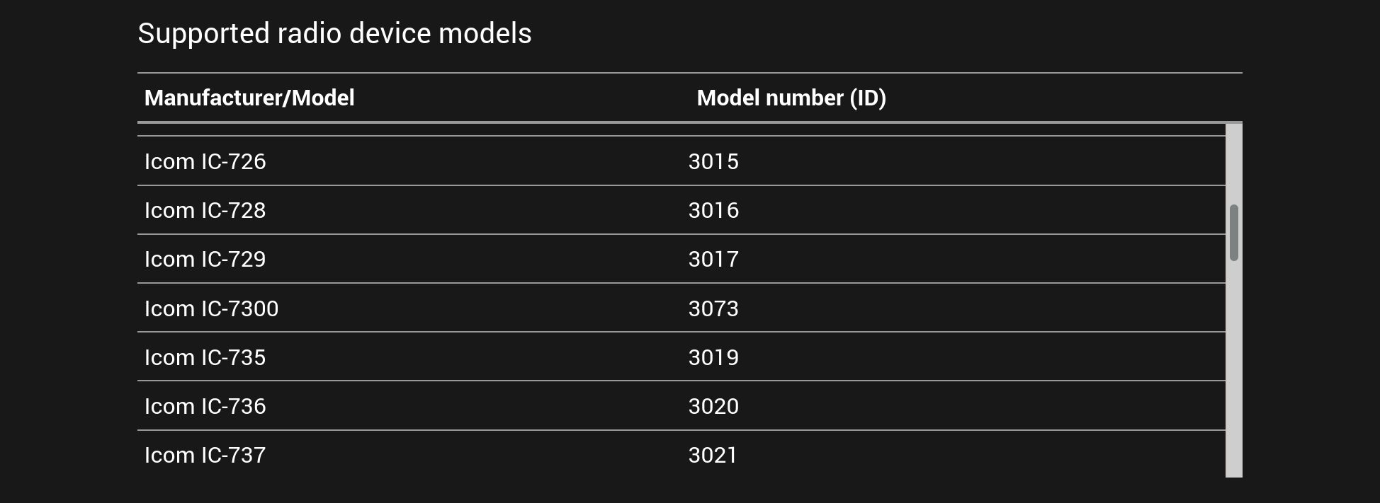
RADIO_MODEL_NUMBER- Radio model number for controlling the radio. Please find the model number of your radio model from the list of supported radio models in the setup user interface (see the screenshot below) or from the documentation on page supported radios. The manufacturers and models are listed alphabetically. Example:3073(for IC-7300)
An example screenshot of the list of supported radio models displayed in the setup user interface:
Radio control configuration
-
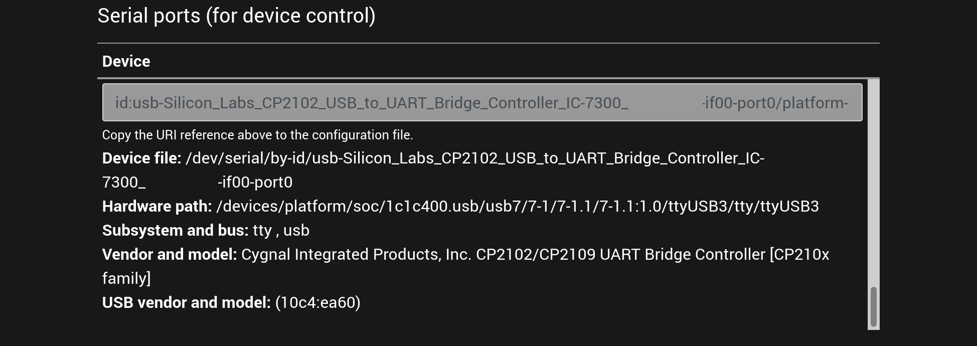
SERIAL_PORT_DEVICE- Radio serial port in URI reference format documented below.The setup user interface lists all detected serial ports and adapters under title
Serial ports (for device control), see the screenshot below. Find the serial port that is connected to the radio from the list of serial ports and copy the text from theURI referencecolumn here. Each URI reference has either anid:prefix.The list of serial ports identifies USB serial port adapters with
tty, usbin theSubsystem, busfield. Radio models with a USB connector will usually have the radio model and some form of serial number in theid:URI reference, although there is no general rule on what the URI references will look like. With multiple radios of the same model or when using USB — RS-232 adapters it is usually not possible to know which serial port is connected to which radio, so you will have to test each URI reference.Example:
id:IC-7300_01234567 -
SERIAL_SPEED- Radio serial port communication speed (baud rate). Choose a speed supported by your radio model. Example:19200
An example screenshot of the list of serial ports displayed in the setup user interface:
Radio audio device configuration
-
AUDIO_INPUT_DEVICE_NAME- Audio input device name (= RX audio, radio speaker output) for Web Radio Control server. Choose the audio input device name connected to the radio model specified above from the setup user interface listing titledAudio inputs (from radio), see the screenshot below.The audio input device name may sometimes contain names of the manufacturer or the radio model to help you identify the correct one. All audio input device names have a prefix of
alsa_input.usbfor USB sound cards.Example:
alsa_input.usb-Burr-Brown_from_TI_USB_Audio_CODEC-00.analog-stereo -
AUDIO_OUTPUT_DEVICE_NAME- Audio output device name (= TX audio, radio microphone input) for Web Radio Control server. Choose the audio output device name connected to the radio model specified above from the setup user interface listing titledAudio outputs (to radio), see the screenshot below.The audio output device name may sometimes contain names of the manufacturer or the radio model to help you identify the correct one. All audio output device names have a prefix of
alsa_output.usbfor USB sound cards.Example:
alsa_output.usb-Burr-Brown_from_TI_USB_Audio_CODEC-00.analog-stereo
An example screenshot of the list of audio input and output devices displayed in the setup user interface:
Save the configuration file
Save the changes you have made to configuration file template in the text editor.
An example of a finished configuration file
The example below contains configuration for an IC-7300 radio.
This configuration file is only an example and cannot be used as it is, because the radio and audio device names depend on the radio equipment and accessories you use. This example serves primarily as a reference for checking what a finished configuration file for controlling a single radio looks like.
server:
  publicHostname: "my.domain.net"
  ipv6: false
  lanMode: false
  apiSecret: "my-password-change-me"

devices:
- id: "ic7300"
  type: "rigctld"
  rigctld:
    localInstance:
      enabled: true
      model: 3073
      rigDevice: "id:IC-7300_01234567"
      serialSpeed: 19200
  media:
    stream:
      audioInputDeviceName: "alsa_input.usb-Burr-Brown_from_TI_USB_Audio_CODEC-00.analog-stereo"
      audioOutputDeviceName: "alsa_output.usb-Burr-Brown_from_TI_USB_Audio_CODEC-00.analog-stereo"
Configuring additional radio settings and remote control of accessories
The pages listed below document additional configuration settings, which you may need depending on the radio model and if you wish to control other accessories, such as rotators and antenna switches.
Additional configuration settings are necessary, if:
-
Radio PTT is controlled via RTS/DTR control lines of an RS-232 serial port
-
You wish to use morse keying (CW) features or an adapter for a physical morse key
-
You use a Dynamic DNS service for the domain name you have chosen and wish to have Web Radio Control update the IP address of the domain name
-
You wish to control an antenna rotator
-
You wish to control an antenna switch
-
The radio indicates that morse key is constantly held down and the radio does not respond to control commands (usually sent via a separate radio control interface)
Documentation for additional configuration settings
Setting up PTT control via serial port
Setting up PTT control via RS-232 serial port RTS/DTR control lines
Configuring CW keyer
Configuring CW keyer for radios with separate CW keyer port connector or for use with a physical morse key adapter
Using dynamic DNS services
Using dynamic DNS service to keep a domain name IP address up-to-date
Controlling antenna rotators
Configuring control of antenna rotators
Controlling antenna switches
Configuring control of antenna switches
Preventing PTT and CW control getting stuck
Turning off RS-232 serial port control lines in case PTT switch or CW keying is stuck