Controlling antenna switches
Configuring control of antenna switches
Web Radio Control can control antenna switches via GPIO pins, which Raspberry Pi exposes in the GPIO header connector. The website pinout.xyz provides a more detailed description of the pins and their uses.
Web Radio Control allows you to control the state of GPIO pins. The voltages of the GPIO pins in Raspberry Pi devices are 3.3V for the ON state and 0V for the OFF state.
NOTE The GPIO pins are very sensitive to voltage and in most devices they are directly connected to the main processor GPIO lines without any additional protection. In order to protect the processor and the GPIO pins, it is necessary to use proper current limiting resistors and optical isolation when connecting the pins to any external device. Also note that the GPIO pins in Raspberry Pi have a maximum source current of 16 mA per pin and total source current of 50 mA for all of the pins.
Copy the example configuration below to a text editor, edit it based on the GPIO pins you will use to control your antenna switch and add the edited configuration to the end of the full configuration file. Follow the instructions below the example on how to fill in the example configuration.
antennaSwitches:
- id: "ANTENNA_SWITCH_ID"
  name: "ANTENNA_SWITCH_NAME"
  description: "ANTENNA_SWITCH_DESCRIPTION"
  defaultChoiceId: "DEFAULT_CHOICE_ID"
  choices:
  - id: "ANTENNA_ID_1"
    name: "ANTENNA_NAME_1"
    description: "ANTENNA_DESCRIPTION_1"
    switch:
      name: "ANTENNA_GPIO_PIN_1"
  - id: "ANTENNA_ID_2"
    name: "ANTENNA_NAME_2"
    description: "ANTENNA_DESCRIPTION_2"
    switch:
      name: "ANTENNA_GPIO_PIN_2"
Filling in the configuration example for antenna switches
Replace the placeholders (e.g. ANTENNA_SWITCH_NAME) in the configuration example using the instructions below.
Pay attention to preserve any double quotes and spaces around the placeholders.
The configuration file format is called YAML, which is sensitive to the number of spaces in the beginning of each line. Please make sure to not change the number of spaces!
Fill in the following details according to the antenna switches and GPIO pins you use and name the choices according to the individual antennas connected to each antenna switch:
-
ANTENNA_SWITCH_ID- An identifier for the antenna switch to be controlled. The identifier is used internally by Web Radio Control to distinguish between antenna switches. You can choose the identifier freely, but it makes sense to use the antenna switch model or some numbering schema as the ID. Note that the ID may only contain characters A-Z, a-z and 0-9. Example:switch1 -
ANTENNA_SWITCH_NAME- Human-readable name of the antenna switch to be displayed in the user interface -
ANTENNA_SWITCH_DESCRIPTION- Human-readable description text for the antenna switch to be displayed in the user interface -
DEFAULT_CHOICE_ID- ID of the antenna that is selected by default in the antenna switch, when no GPIO pin is active. This settings should be left empty (with only double quotes"") if the antenna switch can be used to leave the antenna unselected, usually for the purpose of grounding. If it is not possible to leave the antenna unselected in the antenna switch, this setting specifies the antenna that is selected by default, when the antenna switch receives no control signals.
The list named choices in the configuration specifies the actual antenna choices of the antenna switch. This list
should include mappings between antennas and GPIO pins used to select each antenna. You can defined any number of antennas
for an antenna switch, but each antenna must have a unique ID as identifier.
-
ANTENNA_ID_1/ANTENNA_ID_2/ … - A unique identifier for the antenna. The identifier is used internally by Web Radio Control to distinguish between antennas. You can choose the identifier freely, but it makes sense to use the antenna model or some numbering schema as the ID. Note that the ID may only contain characters A-Z, a-z and 0-9. Example:th7dxThis can also be a number, e.g."1","2", etc. -
ANTENNA_NAME_1/ANTENNA_NAME_2/ … - Human-readable name of the antenna to be displayed in the user interface. -
ANTENNA_DESCRIPTION_1/ANTENNA_DESCRIPTION_2/ … - Human-readable description text for the antenna to be displayed in the user interface. -
ANTENNA_GPIO_PIN_1/ANTENNA_GPIO_PIN_2/ … - The name of the GPIO pin to use to select this antenna. The Web Radio Control setup user interface lists the GPIO pin names under titleExternal hardware control switches(see the screenshot below). For example, the Raspberry Pi GPIO pins have namesGPIOnn, wherennis the pin number, e.g.GPIO17.
Web Radio Control supports controlling multiple antenna switches, so you can defined more than one antenna switch in the list called
antennaSwitches in the configuration.
The screenshot below is an example of the Web Radio Control setup user interface that lists the available GPIO pins and other types of switches (e.g. network-controlled relays) for controlling antenna switches:

An example of a filled-in configuration for a 3-port antenna switch
The example below configures a 3-port antenna switch with the ability to leave the antenna unselected
(defaultChoiceId is empty: ""). The GPIO pin for each antenna is configure using the switch → name setting.
This configuration file is only an example and cannot be used as it is, because the antenna switch details and related GPIO pins depend on the equipment and accessories you use. This example serves primarily as a reference for checking what a finished configuration file for controlling a single antenna switch looks like.
antennaSwitches:
- id: "switch1"
  name: "Antenna switch 1"
  description: "Antenna switch 1 description"
  defaultChoiceId: ""
  choices:
  - id: "1"
    name: "1 - Windom 10-160m"
    description: "Wire antenna"
    switch:
      name: "GPIO17"
  - id: "2"
    name: "2 - TH-7DX"
    description: "Beam for 10, 15 and 20 meters"
    switch:
      name: "GPIO18"
  - id: "3"
    name: "3 - Cushcraft 40-2CD"
    description: "Beam for 40 meters"
    switch:
      name: "GPIO27"
Linking antenna switches to radios
After configuring an antenna switch, you can control the antenna selection in a separate antenna switch view in the Web Radio Control user interface. While this method works well, it may be difficult and time-consuming to switch between the radio and the antenna switch views often while trying to use the radio controls at the same time.
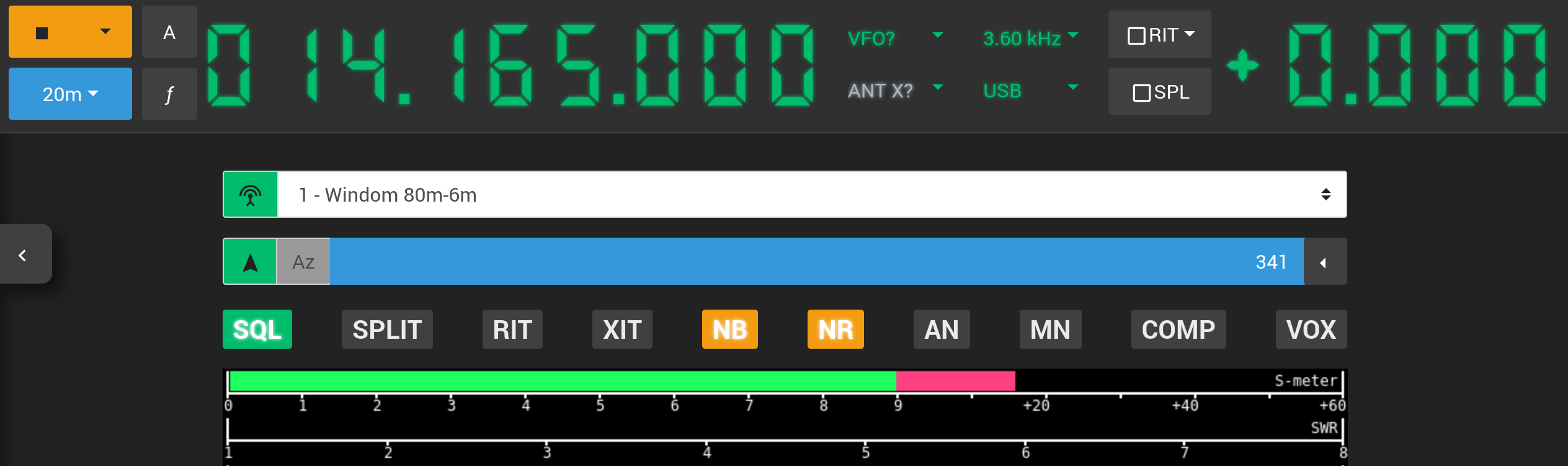
To make antenna switch control faster and easier, Web Radio Control allows you to link antenna switches to one or more radios. When an antenna switch is linked to a radio, a drop-down selector for the antenna switch will appear in the radio control view above the radio meters. The selector lists the available antenna choices for the antenna switch and allows you to change the active antenna simply by selecting one of the antennas in the drop-down selector.
The screenshot below shows an example of how the linked antenna switch drop-down selector appears in the radio control view:
Configuration for radios with a single antenna connector
To link an antenna switch to a radio, you will need to add the following reference to the devices listing for the radio
you wish to link the antenna switch to (pay attention to the number of spaces in the beginning of the lines):
  linkedAntennaSwitches:
- id: "SWITCH_ID"-
SWITCH_ID- The ID of the antenna switch to be linked to the radio. For the example above, it would beswitch1.
Configuration for radios with multiple antenna connectors
Alternatively, if you radio model has multiple antenna connectors, it is possible to define which antenna connector
the antenna switch is connected to. The antenna connector is specified using the antenna numbers listed in the
radio ANT drop-down selector on the right side of the VFO frequency. The number of the first antenna is 1.
To link an antenna switch to a specific antenna connector of a radio, you will need to add the following reference
to the devices listing for the radio you wish to link the antenna switch to
(pay attention to the number of spaces in the beginning of the lines):
  linkedAntennaSwitches:
  - id: "SWITCH_ID"
antenna: ANTENNA_CONNECTOR_NUMBER-
SWITCH_ID- The ID of the antenna switch to be linked to the radio. For the example above, it would beswitch1. -
ANTENNA_CONENCTOR_NUMBER- The number of the antenna connector in the radio to which the antenna switch is connected. Number1is the first connector.
Full configuration example for linking an antenna switch to a radio
The full configuration could look like the example below when the antenna switch is connected to the antenna connector 2 of a radio:
... (continued)
devices:
- id: "radio1-id"
  type: "rigctld"
  rigctld:
    localInstance:
      enabled: true
      model: RADIO_MODEL_NUMBER
      rigDevice: "SERIAL_PORT_DEVICE"
      serialSpeed: SERIAL_SPEED
  linkedAntennaSwitches:
  - id: "switch1"
    antenna: 2
... (continued)

... (continued)
antennaSwitches:
- id: "switch1"
  name: "Antenna switch 1"
  description: "Antenna switch 1 description"
... (continued)