Controlling antenna rotators
Controlling antenna rotators
Web Radio Control uses Hamlib rotctld application to control antenna rotators. Hamlib supports controlling rotator controllers
with serial port, USB or network connection.
The configuration for setting up control for an antenna rotator controller is very similar to the configuration of controlling a radio: each configured rotator needs settings for a unique ID as identifier, the Hamlib rotator controller model number and a reference to the rotator controller serial port or a network address (for a network-based rotator controller).
Add an empty line to the end of the Web Radio Control configuration file, copy the following configuration template to the end of the file and follow the instructions below to fill in the configuration template.
rotatorDevices:
- id: "ROTATOR_ID"
  type: "rotctld"
  rotctld:
    localInstance:
      enabled: true
      model: ROTATOR_MODEL_NUMBER
      rotDevice: "ROTATOR_DEVICE"
      serialSpeed: SERIAL_SPEED
Filling in the configuration example for antenna rotators
Replace the placeholders (e.g. ROTATOR_MODEL_NUMBER) in the configuration example using the instructions below.
Pay attention to preserve any double quotes and spaces around the placeholders.
The configuration file format is called YAML, which is sensitive to the number of spaces in the beginning of each line. Please make sure to not change the number of spaces!
Some of the following placeholders in the configuration file template depend on the rotator controller models in use,
so you will have to look up them in the List devices listing of the setup user interface.
Configuration options
The placeholders to be replaced in the configuration file template are:
Rotator model configuration
-
ROTATOR_ID- An identifier for the antenna rotator to be controlled. The identifier is used internally by Web Radio Control to distinguish between antenna rotators and other devices. You can choose the identifier freely, but it makes sense to use the rotator model as the ID. Note that the ID may only contain characters A-Z, a-z and 0-9. Example:pst61d -
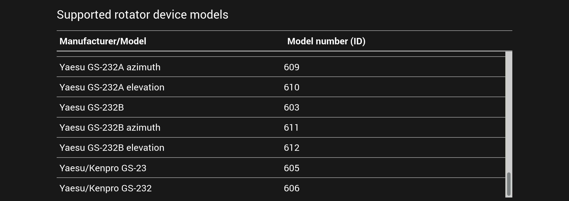
ROTATOR_MODEL_NUMBER- Rotator model number for controlling the rotator. Please find the model number of your rotator controller model from the list of supported rotator models in the setup user interface (see the screenshot below) or from the documentation on page supported antenna rotators. The manufacturers and models are listed alphabetically. Example:1701(for Prosistel antenna rotators)
An example screenshot of the list of supported rotator models displayed in the setup user interface:
Rotator control configuration
-
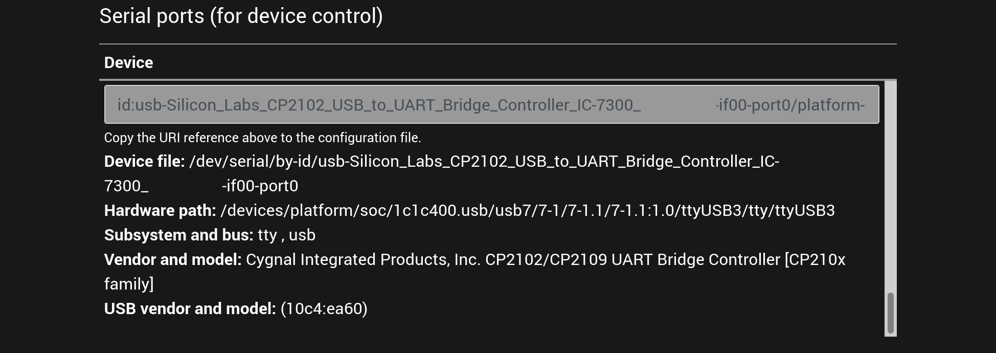
ROTATOR_DEVICE- Rotator controller serial port or network address in URI reference format documented below.The setup user interface lists all detected serial ports and adapters under title
Serial ports (for device control), see the screenshot below. Find the serial port that is connected to the rotator from the list of serial ports and copy the text from theURI referencecolumn here. URI references for serial ports have anid:prefix and network addresses have prefixnet:.The list of serial ports identifies USB serial port adapters with
tty, usbin theSubsystem, busfield. Rotator models with a USB connector will usually have the rotator model and some form of serial number in theid:URI reference, although there is no general rule on what the URI references will look like. With multiple rotators of the same model or when using USB — RS-232 adapters it is usually not possible to know which serial port is connected to which rotator, so you will have to test each URI reference.Example:
id:usb-Prolific_Technology_Inc._USB-Serial_Controller_D-if00-port0For rotator controllers with network connection, use URI references with
net:prefix, e.g.net:rotator(domain name) ornet:192.168.0.81(IP address). -
SERIAL_SPEED- Rotator serial port communication speed (baud rate). Choose a speed supported by your rotator controller model (for rotator controllers with serial port connection only!). Example:9600
An example screenshot of the list of serial ports displayed in the setup user interface:
An example of finished rotator configuration
The example below contains configuration for a a Prosistel PST-61D antenna rotator and controller.
This rotator configuration is only an example and cannot be used as it is, because the rotator configuration depends on the rotator equipment you use. This example serves primarily as a reference for checking what a finished configuration for controlling a single rotator looks like.
rotatorDevices:
- id: "pst61d"
  type: "rotctld"
  rotctld:
    localInstance:
      enabled: true
      model: 1701
      serialSpeed: 9600
      rotDevice: "id:usb-Prolific_Technology_Inc._USB-Serial_Controller_D-if00-port0"
Linking rotators to radios
After configuring a rotator, you can control the rotator in a separate rotator control view in the Web Radio Control user interface. While this method works well, it may be difficult and time-consuming to switch between the radio and the rotator control views often while trying to use the radio controls at the same time.
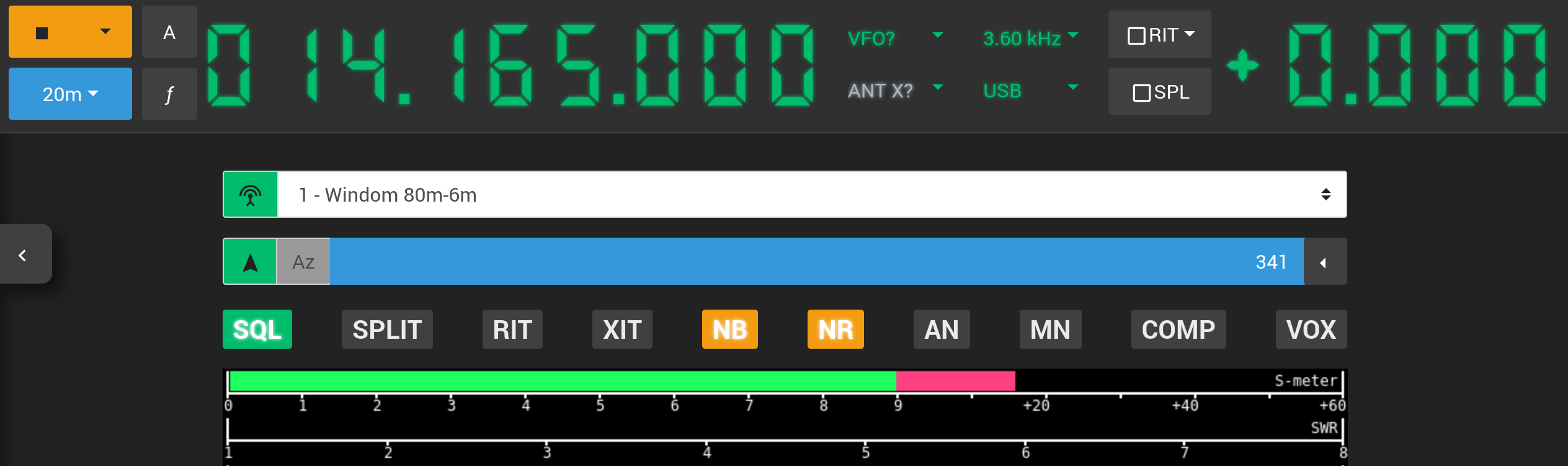
To make rotator control faster and easier, Web Radio Control allows you to link rotators to one or more radios. When a rotator is linked to a radio, a direction indicator for the rotator direction will appear in the radio control view above the radio meters. The indicator displays the current azimuth and/or elevation (depending on rotator type) and allows you to set the azimuth and elevation angles by clicking the respective numbers.
There is also a drop-down menu shortcut to the saved rotator directions on the right side of the indicator.
The screenshot below shows an example of how the direction indicator appears for a linked rotator in the radio control view:
Configuring a linked rotator
To link a rotator to a radio, you will need to add the following reference to the devices listing for the radio
you wish to link the rotator to (pay attention to the number of spaces in the beginning of the lines):
  linkedRotators:
- id: "ROTATOR_ID"-
ROTATOR_ID- The ID of the rotator to be linked to the radio. For the example above, it would bepst61d.
Full configuration example for linking a rotator to a radio
The full configuration could look like the example below:
... (continued)
devices:
- id: "radio1-id"
  type: "rigctld"
  rigctld:
    localInstance:
      enabled: true
      model: RADIO_MODEL_NUMBER
      rigDevice: "SERIAL_PORT_DEVICE"
      serialSpeed: SERIAL_SPEED
  linkedRotators:
  - id: "pst61d"
... (continued)

... (continued)
rotatorDevices:
- id: "pst61d"
  type: "rotctld"
... (continued)